58 / GB
Refrigerant recover
If it becomes necessary to disconnect the refrigerant connec-
tions for unit repair, removal or disposal, in order to avoid re-
frigerant loss to the atmosphere, the pump down operation
must be carried out.
Pump-down is an operation intended to collect all the system
refrigerant in the outdoor unit:
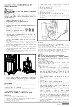
1. unscrew the caps of the 3-way valve outlets.
2. Set the unit in cooling mode through parameter 17.8.5 on
the remote control (check compressor works) and leave on
for a few minutes.
3. connect the manometer.
4. close the smaller valve.
5. When the pressure gauge indicates «0» also close the other
valve and switch off immediately.
6. close the valve caps.
After disconnection, protect valves and tubing ends from dust.
After refrigerant recover operation, the outdoor unit is in Hard
Fault status (Recovery is done with the parameter 17.17 Service
Reset).
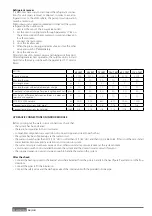
HYDRAULIC CONNECTIONS ON INDOOR MODULE
Before carrying out the water circuit connections, check that:
• the system has been cleaned
• there are no impurities in the circuit water
• compatible components are used (do not connect copper and steel to each other)
• the system has been hooked up via the water circuit
• the water is never harder than 20°F (11,2 °dH) or softer than 12°F (6,7 °dH), and that its pH is 6.6 to 8.5. If this is not the case, install
water treatment to prevent incrustations and corrosion in system.
• the water circuit pressure never exceeds 5 bar, otherwise install a pressure reducer at the system’s intake
• a disconnector with cock is installed between the system and the domestic water circuit (if present)
• the supplied expansion vessel is large enough to handle the water in the system
After the check:
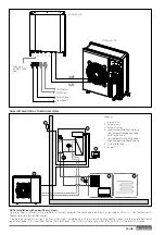
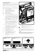
• Connect the heating system to the internal unit where indicated from the points A and B in the next fi gure. Pay attention to the fl ow
directions.
• Connect the pipes to fi ll the installation.
• Connect the safety valve and the discharge valve of the internal unit with the provided silicone pipe.
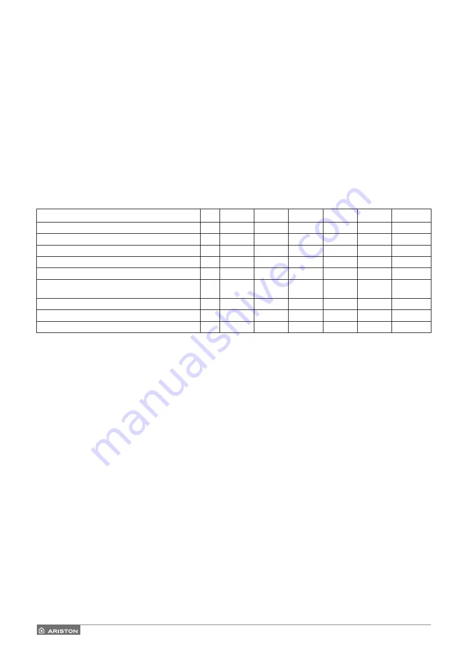
MODEL
40 S EXT
50 S EXT
70 S EXT
70 S-T EXT
90 S-T EXT
110 S-T EXT
Nominal charge
g
2300
2300
3080
3080
4300
4300
Max length pipes
m
30
30
30
30
30
30
Min length pipes
m
5
5
5
5
5
5
Max length pipes without additional gas charge
m
20
20
20
20
20
20
Additional refrigerant charge (for pipe length above 20 m)
g/m
40
40
40
40
40
40
Max height diff erence between outdoor & indoor unit
(positive and negative)
m
10
10
10
10
10
10
ESTER OIL VG74 volume
ml
500
500
670
670
1400
1400
Connections dimensions (inlet pipe)
inch
5/8
5/8
5/8
5/8
5/8
5/8
Connections dimensions (outlet pipe)
inch
3/8
3/8
3/8
3/8
3/8
3/8
Summary of Contents for 3300919
Page 8: ...8 IT 1106 383 1016 670 ø 10 374 1506 383 1016 670 ø 10 374 70 S 70 S T EXT 9 0 110 S T EXT ...
Page 22: ...22 IT SCHEMA ELETTRICO QUADRO UNITÀ ESTERNA 3 ph 1 ph ...
Page 50: ...50 GB 1106 383 1016 670 ø 10 374 1506 383 1016 670 ø 10 374 70 S 70 S T EXT 90 110 S T EXT ...
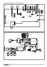
Page 64: ...64 GB 3 ph 1 ph ELECTRICAL SCHEME BOX OF EXTERNAL UNIT ...
Page 86: ...86 IT ...
Page 87: ...87 IT ...


