59 / GB
A
B C D E F
5/8”
3/8”
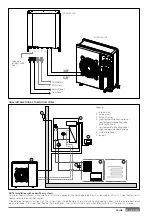
INTERNAL UNIT
VE
1
6
4
5
2
3
7
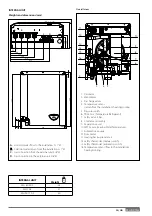
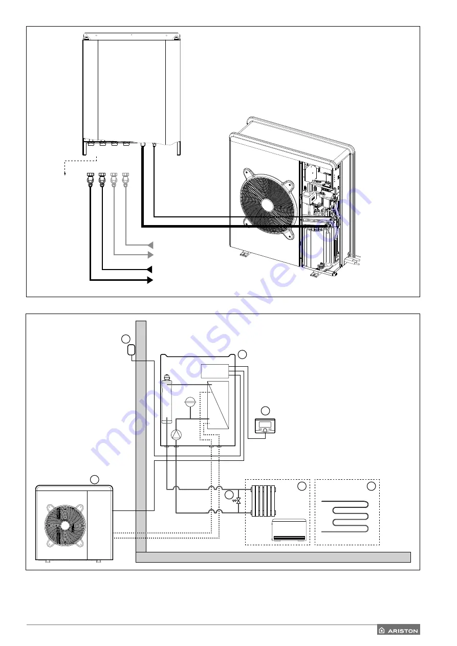
Legend:
1. Internal unit
2. External unit
3. External sensor
4. High-temperature heating zone /
Low temperature cooling zone
(with fan coil unit)
5. Low temperature heating zone /
High-temperature cooling zone
6. System interface
7. By pass
Return Zone 1
DHW Return
Flow Zone 1
DHW Flow
Discharge
of safety valve
3 bar
EXTERNAL UNIT
FINAL INSTALLATION OF THE WHOLE SYSTEM
NOTE: Installation with under-fl oor systems
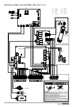
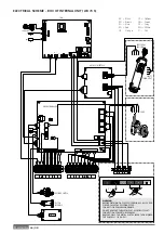
For under-fl oor installations, make sure to install a safety device on the heating delivery circuit, as required by DTU 65.11. For the thermostat
hookup, refer to “Electrical connections”.
If the delivery temperature is too high, the system stops in both domestic hot water and heating/cooling modes, and the remote control will
report error code 116 “Under-fl oor heating thermostat open”. The system will start again when the manual re-arm thermostat is closed.
Summary of Contents for 3300919
Page 8: ...8 IT 1106 383 1016 670 ø 10 374 1506 383 1016 670 ø 10 374 70 S 70 S T EXT 9 0 110 S T EXT ...
Page 22: ...22 IT SCHEMA ELETTRICO QUADRO UNITÀ ESTERNA 3 ph 1 ph ...
Page 50: ...50 GB 1106 383 1016 670 ø 10 374 1506 383 1016 670 ø 10 374 70 S 70 S T EXT 90 110 S T EXT ...
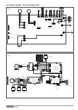
Page 64: ...64 GB 3 ph 1 ph ELECTRICAL SCHEME BOX OF EXTERNAL UNIT ...
Page 86: ...86 IT ...
Page 87: ...87 IT ...

