72 / GB
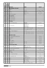
17.7.2 Force Hp Cool
Activate the heat pump in cooling mode
17.7.3 Rating Heating Mode
17.7.4 Rating Cooling Mode
17.7.5 Fixed compressor frequency
Defi ne the compressor frequency during the working mode
of the heat pump selected by the parameters 17.7.1 or 17.7.2.
In manual mode the heat pump keeps the protection logics
active, therefore the compressor frequency might be diff erent
from the set one.
Turn the knob and select:
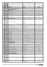
17.8
Test & Utilities
Press the OK button to confi rm.
Turn the knob and select:
17.8.0 Air-purge
function
Active the air purge cycle of the system; the air purge duration
is 18 minutes.
Press the OK button to confi rm. Turn the knob and select:
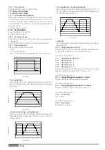
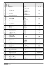
17.8.1 Floor drying cycle
defi ne the fl oor drying cycle mode:
- 0. OFF
- 1. Functional Heating
(fl oor drying done at fi xed temperature of 55°C for 6 days)
15
20
25
30
35
40
45
50
55
60
0 1 2 3 4 5 6 7 8 9 10
- 2. Curing Heating
(fl oor drying done with variable temperature from 25°C to
55°C according to the profi le reported in the picture below
for 18 days)
15
20
25
30
35
40
45
50
55
60
0 2 4 6 8 10 12 14 16 18 20
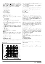
- 3. Functional H Curing Heating
(fl oor drying done at fi xed temperature of 55°C for 6days and
then with variable temperature from 25°C to 55°C for the fol-
lowing 18 days)
15
20
25
30
35
40
45
50
55
60
0 5 10 15 20 25 30
- 4. Curing H Functional Heating
(fl oor drying done with variable temperature from 25°C to
55°C for the fi rst 18 days and then at fi xed temperature of
55°C for the following 6 days)
15
20
25
30
35
40
45
50
55
60
0 5 10 15 20 25 30
- 5. Manual
(fl oor drying done at the setpoint temperature set by the pa-
rameter 17.3.9)
17.8.5 Refrigerante Recover Cycle
Activate this function to recover the refrigerant gas before eve-
ry maintenance operation on the refrigerant circuit.
Turn the knob and select:
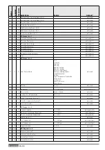
17.9
Energy Manager Statistics
17.10
HP Diagnostics - 1
17.11
HP Diagnostics - 2
17.12
HP Diagnostics - 3
17.13
HP Diagnostics - 4
Displays the characteristic information of the heat pump (tem-
peratures, water fl ow switch status, HP status, etc).
Turn the knob and select:
17.14 Energy Manager Diagnostics -1 Input
Displays the values of the system board inputs
Turn the knob and select:
17.15 Energy Manager Diagnostics - 2 Output
Displays the values of the system board outputs
Turn the knob and select:
17.16 Error
History
Last 10 Errors.
Turn the knob and select:
17.17 Reset
Menu
Reset Factory Settings.
Temper
atur
e °C
Period (days)
Temper
atur
e °C
Period (days)
Temper
atur
e °C
Period (days)
Temper
atur
e °C
Period (days)
Summary of Contents for 3300919
Page 8: ...8 IT 1106 383 1016 670 ø 10 374 1506 383 1016 670 ø 10 374 70 S 70 S T EXT 9 0 110 S T EXT ...
Page 22: ...22 IT SCHEMA ELETTRICO QUADRO UNITÀ ESTERNA 3 ph 1 ph ...
Page 50: ...50 GB 1106 383 1016 670 ø 10 374 1506 383 1016 670 ø 10 374 70 S 70 S T EXT 90 110 S T EXT ...
Page 64: ...64 GB 3 ph 1 ph ELECTRICAL SCHEME BOX OF EXTERNAL UNIT ...
Page 86: ...86 IT ...
Page 87: ...87 IT ...

