83 / GB
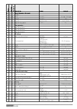
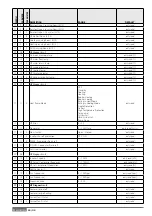
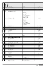
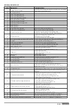
ERROR
DESCRIPTION
TROUBLESHOOTING
1
14
Outdoor Sensor Damaged
Activation of thermoregulation based on outdoor sensor and outdoor
sensor not connected or damaged
4
20*
Bus supply overload
7
01
Zone1 Send Probe Damaged
7
02
Zone2 Send Probe Damaged
7
03
Zone3 Send Probe Damaged (N/A)
7
11
Zone1 Return Probe Damaged
7
12
Zone2 Return Probe Damaged
7
13
Zone3 Return Probe Damaged (N/A)
7
22
Zone2 Overheat
7
23
Zone3 Overheat
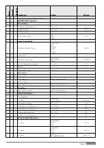
9
02
System fl ow sensor damaged
Flow sensor not connected or damaged
9
03
System return sensor damaged
Return sensor not connected or damaged
9
10
HP communication error
- Check the wiring connection of the modbus cable.
- Red led on TDM not blinking-> change TDM control board
9
23
Low pressure error
Check water leakage of the hydraulic circuit
- Water pressure switch damaged
- Wiring of water pressure switch damaged
9
24
Ebus Communication error between EM and TDM
- Check wiring connection between TDM end Energy Manager
9
33
Overheat
- Check water fl ow of the heating circuit
9
34
DHW Tank sensor damaged
- DHW tank sensor not connected or damaged
9
35
Tank overtemperature
- Check 3-way valve (DIV1) blocked in DHW position
9
36
Floor Thermostat 1 error
- Check water circulation of the underfl oor zone
9
37
No circulation error
- Check main circulation activation
- Check water fl ow sensor detection by par. 17.11.3
9
38
Anode Fault
Check anode connection
- Check water presence in the tank
- Check anode status
9
39
HP error **
See inverter error list
9
40
Hydraulic scheme not defi ned
- Hydraulic scheme not selected by parameter 17.2.0
9
41
HIV IN1 not defi ned
Function not selected by parameter 17.1.0
9
42
HIV IN2 not defi ned
Function not selected by parameter 17.1.1
9
44
Cooling overtemperature
- Check water fl ow of the cooling circuit
9
45
Flow switch stuck
Check if main circulation is active before the heat request
- Check the water fl ow detection by water fl ow sensor (see par. 17.11.3)
before the heat request
9
46
HP compressor error
Check compressor frequency (par 17.12.1) after the end of heat request
9
55
Water fl ow switch
Check the fl ow temperature sensor and return temperature sensor
placement.
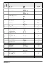
2
P2
Antilegionella not completed
Antilegionella setpoint temperature not reached in 6 hours
- Check DHW tapping during antilegionella cycle
- Check fl ow temperature during antilegionella cycle
- Check heating resistors activation
2
P3
DHW boost: comfort setpoint not reached
DHW comfort setpoint not reached during boost cycle.
- Check DHW tapping during boost cycle
- Check fl ow temperature during boost cycle
- Check heating resistors activation
2
P4
Second thermostat of resistance (manual)
- Check main circulation activation
- Check water fl ow by par 17.11.3
- Check safety thermostat status and wirings
2
P5
First thermostat of resistance (auto)
Check main circulation activation
- Check water fl ow by par 17.11.3
- Check safety thermostat status and wirings
2
P6
Night tariff contact not present
- Par 17.5.2 = HP-HC or HP-HC 40°C and par. 17.1.0 = Absent
2
P7
Precirculation Error
Water fl ow not detected for 5 times during pre-circulation
2
P9
SG ready input confi guration not completed
Just one of par 17.1.0 or 17.1.1 is defi ned as SG Ready input
INTERNAL UNIT ERROR LIST
Summary of Contents for 3300919
Page 8: ...8 IT 1106 383 1016 670 ø 10 374 1506 383 1016 670 ø 10 374 70 S 70 S T EXT 9 0 110 S T EXT ...
Page 22: ...22 IT SCHEMA ELETTRICO QUADRO UNITÀ ESTERNA 3 ph 1 ph ...
Page 50: ...50 GB 1106 383 1016 670 ø 10 374 1506 383 1016 670 ø 10 374 70 S 70 S T EXT 90 110 S T EXT ...
Page 64: ...64 GB 3 ph 1 ph ELECTRICAL SCHEME BOX OF EXTERNAL UNIT ...
Page 86: ...86 IT ...
Page 87: ...87 IT ...

