11
product description
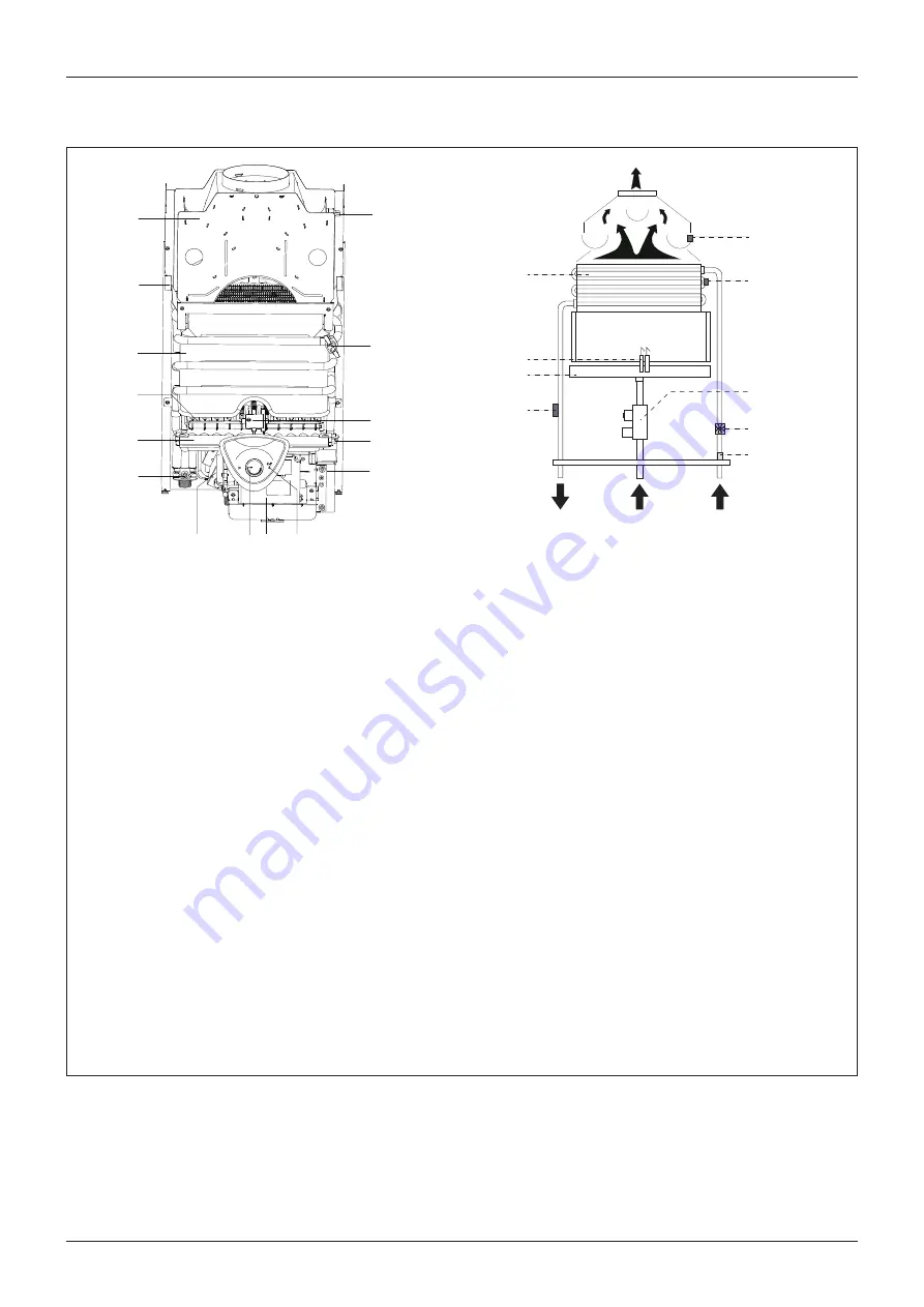
Overall view
Water circuit diagram
B.
Hot water outler 1/2”
C.
Ingresso Gas 1/2”
D.
Cold water inlet 1/2”
1. Combustion Hood
2. Frame
3. Heat exchanger
4. Burner
5. Gas collector
6. Hot water temperature sensor
7. Gas valve
8.
Switch ON/OFF and D.H.W temmperature knob
9. P.C.B. box
10. L.E.D.:
red - errors signal
orange - adjustment in progress
11. Ignition P.C.B.
12. Water
fl
ow switch
13. Ignition and detection electrode
14. Overheat thermostat
15. Fume sensor
16. Cold water inlet
fi
lter
1
2
3
4
5
6
7
8 9
10
11
12
13
14
15
B
C
D
3
13
4
6
16
7
14
15
12


