Page 16
Installation manual for the CD72/95/15012
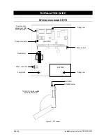
W
IRING DIAGRAMS
CD95/150
Power supply adjustment
(DO NOT ADJUST)
LED
“power on”
Fixing hole
Memory card
connector
Dialler connector
Input expander
socket
Main PCB
Fixing hole
RD6203 Dialler
BATTERY
Fixing hole
Mains cable
entry
Transformer
Cable entries
Output expander
socket
Fixing hole
Printer connector
RS232
Fold lid down
(CD95)
Figure 7. CD95 cabinet
Power supply adjustment
(DO NOT ADJUST)
Fixing hole
Dialler connector
Memory card
selector
Dialler connector
Output expander
socket
Printer connector
RS232
Mains cable
entry
Fuse holder
Transformer
Screw holes for cover
Wall fixing holes
Cable fixing
points
BATTERY
RD6203
Dialler
Main PCB
Lift up
Pull forward
Opening the cabinet
Unscrew the screws (2x)
Remove earth connection
Figure 8. CD150 cabinet
Summary of Contents for Advisor CD15012
Page 1: ...142938999 1 Installation Manual Software from Version V6 0 ADVISOR CD 7212 CD95 15012 ...
Page 4: ...Page 4 Installation manual for CD72 95 15012 ...
Page 34: ...Page 34 Installation manual for the CD72 95 15012 ...
Page 35: ...Installation manual for the CD72 95 15012 Page 35 ...
Page 36: ...Page 36 Installation manual for the CD72 95 15012 ...
Page 38: ...Page 38 Installation manual for the CD72 95 15012 ...
Page 39: ...Installation manual for the CD72 95 15012 Page 39 ...
Page 40: ...Page 40 Installation manual for the CD72 95 15012 ...


