Installation manual for the CD72/95/15012
Page 23
C
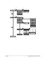
ONNECTING A DETECTOR WITHOUT MEMORY
Input zone
Power supply
4k7
4k7
S
S
A
A
7
6
5
4
3
2
1
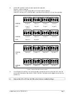
Figure 16. Dual loop Connecting a detector without memory
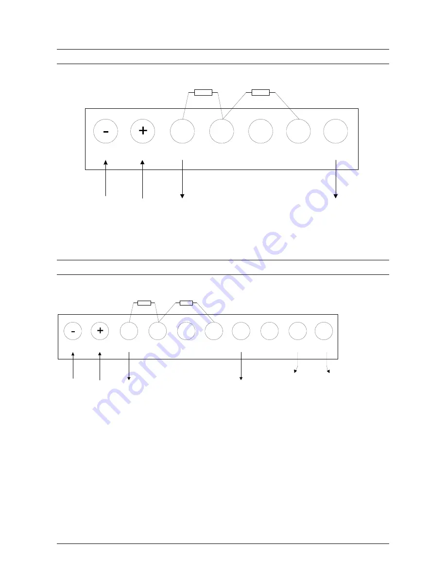
C
ONNECTING A DETECTOR WITH
L
ATCH
Power supply
Input zone
Output “Latch”
Output “Walk test”
M
W
S
S
A
A
4k7
4k7
1
2
3
4
5
6
7
8
9
10
Figure 17. Dual loop Connecting a detector with latch
Note:
Before connecting, the cable between terminal 2 and terminal 10 should be removed!
Summary of Contents for Advisor CD15012
Page 1: ...142938999 1 Installation Manual Software from Version V6 0 ADVISOR CD 7212 CD95 15012 ...
Page 4: ...Page 4 Installation manual for CD72 95 15012 ...
Page 34: ...Page 34 Installation manual for the CD72 95 15012 ...
Page 35: ...Installation manual for the CD72 95 15012 Page 35 ...
Page 36: ...Page 36 Installation manual for the CD72 95 15012 ...
Page 38: ...Page 38 Installation manual for the CD72 95 15012 ...
Page 39: ...Installation manual for the CD72 95 15012 Page 39 ...
Page 40: ...Page 40 Installation manual for the CD72 95 15012 ...

