ARITERM SWEDEN AB
Installation, Operation and Maintenance - 2007.10.26- 4/12
OPERATING PRINCIPLE
Small dimensions for easy installation
Th
anks to its modest dimensions Biomatic 20 can be installed in boiler rooms that
would normally be considered too small.
Most of the piping connections are placed on top of the boiler. Th
e terminal block for
electric installation is accessible from the control panel. Service work is facilitated by
the fact that all connections and components are easily accessible from the front.
Hot tap water
Th
e effi
cient plate heat exchanger will ensure that you always get “fresh” hot tap water.
A strainer has been installed in the cold water line to prevent the heat exchanger from
becoming clogged (the water quality should be checked).
Th
e internal circulation pump is controlled by a fl ow switch, fi tted on the hot water
outlet pipe. Th
e whole heat-exchanger package is located behind the electric panel and
is easily accessible for service work.
ATTENTION! Before servicing, disconnect the power to the boiler by switching
off the mains switches. Work on the boiler may only be carried out by a quali
fi
ed electrician.
1
Flow switch
cw
hw
Strainer
2
Front view of the heat exchanger
installation for hot tap water.
1. Plate heat exchanger
2. Internal circulation pump
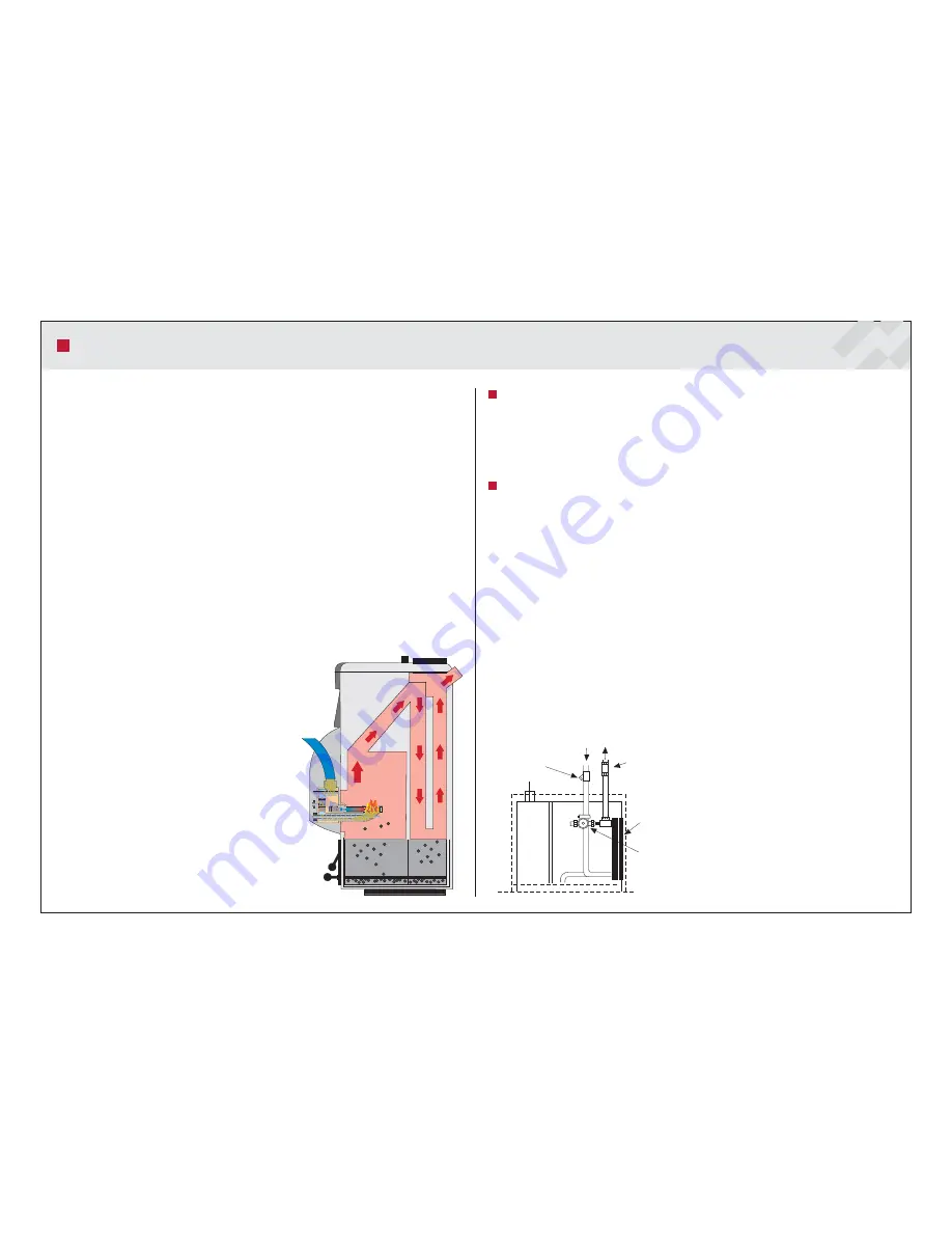
Biomatic, the new generation pellet boiler, is specially designed for pellet burning;
to reduce the formation of soot layers on the convection surfaces as far as
possible, the boiler is equipped with upright convection tubes.
Biomatic is equipped with an oversized ash pan to facilitate care and maintenance.
Sweeping primarily takes place from the soot-hatch on top of the boiler and
through the door of the re-box where the burner is placed.
Th
e boiler is primarily designed for pellet fuel. A 6 kW electric heating element has
been installed for backup purposes.
Biomatic consists of a fuel chamber with fl ue, which is enclosed by a water-fi lled jacket
holding 140 litre. When pellet fuel is burnt, the heat generated by the burner is trans-
ferred directly to the boiler water, which in turn transfers heat to the hot water system
via a heat exchanger. Th
e same principle largely applies when heat is generated by the
electric heating element, but for a somewhat reduced hot water capacity. Th
e heat for
the radiator system is transferred via a 4-way shunt valve. In the shunt valve the boiler
water is mixed with return water from the radiators so that a constant, correct tempe-
rature can be maintained in the radiators in relation to the outdoor temperature. Th
is
is a means to achieve better heating economy. Th
e shunt valve can be regulated either
manually or automatically with a regulating device (optional).


