19
P1
230 VAC
50Hz
T2
T1
P3
T6
2.
3.
4.
1.
CONTENT OF DELIVERY AND INSTALLATION
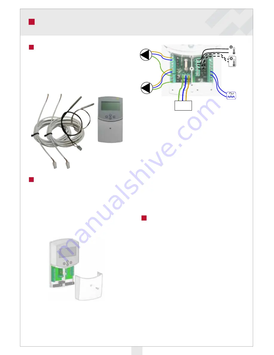
The delivery includes:
1. Control unit
2. Flue gas sensor
3. Boiler water sensor
4. Extension cable
Installation
It is preferable to place the control unit in
a location where no extension is required
for the cable of the flue gas or boiler water
sensors. The extension cable for flue gas and
boiler water sensor is 4 m long.
1. Remove control unit lid.
2. Fluegas fan, loading pump, temperature
sensors and 230 VAC voltage input are
connected to the terminal strips under-
neath the control unit lid.
P1=Flue gas fan
P3=Loading pump
T1=Flue gas sensor
T2=Boiler water sensor
T6=Active combustion alert from the pellet
burner (voltage-free input)
NOTE: If the pellet burner being used
cannot supply voltage-free contact data, this
data can be accessed from the pellet burner’s
flue gas fan via a supplementary relay. The
relay should be operable in the voltage area
100–230 VAC. The fan control unit input is
controlled by a normally open
NO
switch.
Operation mode Wood
When the fan is started in the wood bur-
ning mode, a delay period starts (factory
setting Fan delay time 15 minutes, can be
set between 3 and 15 minutes). During this
delay period, the left top corner of the screen
displays a figure that tells you how many
minutes are left of the delay period.
While the delay period lasts, the flue gas
temperature will rise above the setting tempe-
rature, and a flame icon will appear inside the
boiler icon on the screen. The fan will run for
as long as the flue gas temperature is above
this limit value (settings Fan temp. limit).
Summary of Contents for Vedo
Page 1: ...INSTALLATION OPERATION AND MAINTENANCE Ariterm Vedo ...
Page 23: ...23 MANUFACTURES DECLARATION ...
Page 24: ...24 NOTES ...
Page 25: ...25 NOTES ...
Page 26: ...NOTES ...
Page 27: ...27 NOTES ...


