14
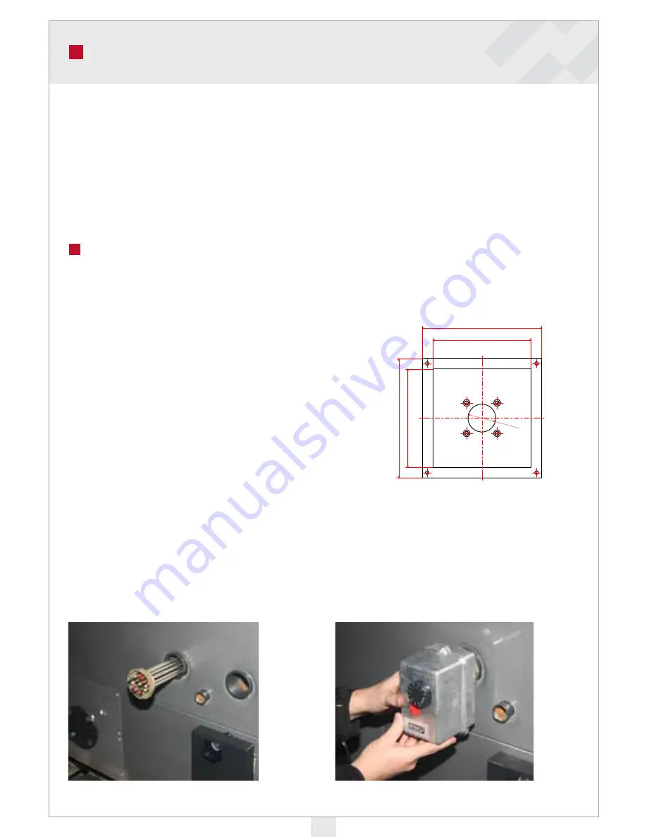
The burner is installed to the burner opening on the side of the boiler. MultiJet burner fits
directly to the opening. Burner flanges for BioJet and HakeJet burners, Axon/PX52-pellet
burners and oil burners (BioComp 60 only) are available as accessories.
The gap between the burner and the flange must be sealed with heat resistant sealant paste.
Burner installation and use according to burner manual.
Alternative heating methods
With an oil burner:
An oil or gas burner can be installed into the burner hatch with oil burner accessories. A flange
with a brick is available for BioComp 60 kW. The brick has an opening which is 100 mm in dia-
meter.
Note! An oil burner cannot be used simultaneously
with a bio burner.
With electricity:
An electric resistance (6 or 9 kW) can be installed into the DN 50 connection on the side of the
boiler (drawings on page 6, position 14). The electric resistance is equipped with a regulating/
overheating thermostat TY3. More detailed installation instructions are supplied with the ther-
mostat.
Fuse sizes: 6 kW resistance 3x10 A and 9 kW resistance 3x16 A.
Power supply: 400 V, 3~, 50 Hz
NOTE! A safety switch must be installed to the resistance power supply.
BURNER INSTALLATION
1. Installation of the resistance
2. Installation of the thermostat
Summary of Contents for BioComp 120 kW
Page 1: ...INSTALLATION OPERATION AND MAINTENANCE For a sustainable future BioComp 40 150 kW ...
Page 12: ...12 ...
Page 22: ...22 DECLARATION OF CONFORMITY ...
Page 28: ...28 NOTES ...
Page 29: ...29 NOTES ...
Page 30: ...NOTES 30 ...
Page 31: ...31 NOTES ...


