background image

14

LABEL AND COMPLIANCE INFORMATION

We promise to continue compliance of WEM-TK module to the FCC rules; we keep to advise our
clients’ host product with a physical or e-label stating “Contain FCC ID” on their finished products.

INFORMATION ON TEST MODES AND

ADDITIONAL TESTING REQUIREMENTS

The user of WEM-TK module needs to follow installation and design guide; there is no extra
information to users on how to configure test modes for host product evaluation for different
operational conditions for a stand-alone modular transmitter in a host, versus with multiple,
simultaneously transmitting modules or other transmitters in a host.

FCC PART 15 SUBPART B DISCLAIMER

FCC Information to Users
This equipment has been tested and found to comply with the limits for a Class B digital devices,
pursuant to Part 15 of the FCC Rules. These limits are designed to provide reasonable protection
against harmful interference in user’s installation. This equipment generates, uses, and can radiate
radio frequency energy and, if not installed and used in accordance with the instruction manual, may
cause harmful interference to radio communications. However, there is no guarantee that
interference will not occur in a particular installation. If this equipment does cause harmful
interference to radio or television reception, which can be determined by turning the equipment off
and on, the user is encouraged to try to correct the interference by one or more of the following
measures:
Reorient or relocate the receiving antenna.
Increase the separation between the equipment and receiver.
Connect the equipment into an outlet on a circuit different from that to which the receiver is
connected.
Consult the dealer or an experienced radio/TV technician for help.

Summary of Contents for WEM-TK TL8715AQ

Page 1: ...UM ARK Intelligence Co Ltd www ark intell com WEM TK USER MANUAL Model TL8715AQ ...

Page 2: ...ay make improvements and or changes in this document or in the product described in this document at any times This document could include technical inaccuracies or typographical errors REVISION HISTORY Revision Date Remark Version 1 0a 2020 10 22 Initialed version Version 1 1a 2021 01 04 Content optimized ...

Page 3: ... DESCRIPTION 4 INSTALLATION 7 SPECIFICATION 7 FCC RULES 11 LIMITED MODULE PROCEDURES 11 RF EXPOSURE CONSIDERATIONS 12 ANTENNAS 12 LABEL AND COMPLIANCE INFORMATION 14 INFORMATION ON TEST MODES AND ADDITIONAL TESTING REQUIREMENTS 14 FCC PART 15 SUBPART B DISCLAIMER 14 ...

Page 4: ...ral main stream HD CIS for camera vision application Wi Fi single on chip system platform providing H 264 video compression ISP image handling engine audio codec and 802 11n Wi Fi connectivity Maximum 1080p30 video capability RTOS Real Time Operation System ultra fast system response best solution for event driven system design Support high speed peripheral interface Well tested and calibrated bef...

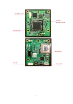
Page 5: ...Fi Xtal performing main system features with 802 11n wireless connectivity The carrier board carries Wi Fi module and own DC DC conversion circuit to downgrade external 12Vdc to 3 3Vdc to supply Wi Fi module Wi Fi RF path is directly driven from RTL8715 SoC and can connect standard Wi Fi antenna ...

Page 6: ...6 Wi Fi module DC power input microSD slot microUSB RESET IPEX4 for external antenna ...

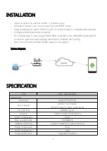
Page 7: ...for connection system will automatically reboot when complete Wi Fi setting Insert microSD card if needed 256GB capacity card support System diagram SPECIFICATION ITEM SPEC DESCRIPTION Main Board Main Chip Realtek RTL8715AQ Kernel design WEM 3 mini module RTL8715 based 2 4GHz single band Wi Fi RF XTal 40MHz crystal Antenna 2dBi omnidirectional antenna Video compression H264 Max resolution fps HD10...

Page 8: ... test system was pre scanning tested base on the consideration of following EUT operation mode or test configuration mode which possible have effect on EMI emission level Each of these EUT operation mode s or test configuration mode s mentioned above was evaluated respectively RADIATED EMISSION TEST BELOW 1GHz Pre Scan has been conducted to determine the worst case mode from all possible combinati...

Page 9: ...ential installation This equipment generates uses and can radiate radio frequency energy and if not installed and used in accordance with the instructions may cause harmful interference to radio communications However there is no guarantee that interference will not occur in a particular installation If this equipment does cause harmful interference to radio or television reception which can be de...

Page 10: ...ting their end product for any additional compliance requirements required with this module installed for example digital device emissions PC peripheral requirements etc Validity of using the module certification In the event that these conditions cannot be met for example certain laptop configurations or co location with another transmitter then the FCC authorization for this module in combinatio...

Page 11: ...ps Antenna type Onboard IPEX 4 connector for external antenna 2 Wi Fi TX output power MODULATION typical PWR UNIT 2 4GHz CCK 11M 17 dBm 2 4GHz OFDM 54M 15 dBm 2 4GHz MCS7 HT20 14 dBm 2 4GHz MCS7 HT40 14 dBm 3 Wi Fi RX sensitivity MODULATION max SENSITIVITY UNIT 2 4GHz CCK 1M 91 dBm 2 4GHz OFDM 6M 87 dBm 2 4GHz MCS7 HT20 67 dBm LIMITED MODULE PROCEDURES The WEM TK module is limited module which is ...

Page 12: ...nfigurations can be found at FCC website by entering the FCC ID number on the device This Mobile device has been evaluated for and shown compliant with the FCC RF Exposure limits FCC Compliance Statement You are cautioned that changes or modifications not expressly approved by the part responsible for compliance could void the user s authority to operate the equipment This device complies with Par...

Page 13: ... 6 1 2 2500 11 3 1 7 V1 0 Frequency MHz Efficiency dB Efficiency Peak Gain dBi 2400 MHz 2 55 55 65 3 08 2450 MHz 1 97 63 57 3 69 2500 MHz 2 41 57 45 2 90 Trace antenna designs Condition free space Antenna type PIFA Frequency range 2 4GHz Return lose 10dB Efficiency 50 Polarization linear Input impedence 50 ohm Antenna size 30 6 x 11 2 x 0 6 mm cable length 90mm cable type diameter 0 81 Return loss...

Page 14: ...B digital devices pursuant to Part 15 of the FCC Rules These limits are designed to provide reasonable protection against harmful interference in user s installation This equipment generates uses and can radiate radio frequency energy and if not installed and used in accordance with the instruction manual may cause harmful interference to radio communications However there is no guarantee that int...

Page 15: ...osure Statement This equipment complies with FCC radiation exposure limits set forth for an uncontrolled environment This equipment should be installed and operated with minimum distance 20cm between the radiator your body ...

Reviews: