background image

Arkbird FPV 


-7- 


3


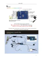
5V Dual Power Supply


On broad OSD 12V to 5V regulator , with 5V BEC(form ESC) supplies power to the CPU module at the same time.   


If  OSD  function  is  not  used,  please  plug  in  OSD  12V  power  as  well  to  prevent  a  lack  of  power  supply  for  5V 

electronic speed controller. 


4

 Installation: 


1.     

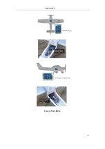
The pins of Servo & Radio RX 

shall stay forward (toward flying direction), the side with soldering dot shall 

be 

upward

 or 

Vertical toward right wing

Default is level installation


2.     

Keep  GPS  antenna  upward  placed  and  away  from  interference  sources  such  as  image  transmission  and 

camera.


3.      Put  on  heat-shrink  tubing,  fix  by  sponge  and  cable  tie.  Please  keep  away  from  motor  to  avoid  vibration 

which will reduce the accuracy of sensor.   

4.      While using on 

flying wing

, connect channel 1 output to right servo and connect channel 2 output to left 

servo. 

DISABLE the mix function from transmitter, switch Dip switch 4 to “0” to enable flying wing mix.


5. 

When using on V-wing, connect Channel 2 output to the right V-wing; attach Channel 4 to the left V-wing. 

DISABLE the mix function from transmitter, enable V-wing mix in the OSD menu(Flight Parameters).


6.      While using on 3-channel plane, connect Channel 1 output to rudder to steering. 

7.      When setting return-to-home, please take off propellers for safety concern. 

Summary of Contents for FPV OSD V3.1028

Page 1: ... Hover mode 7 Fence mode Auto Switching to Return to Home Mode while flying out of the rectangle area specified 8 4 Way point flight coordinate set by radio stick 9 Launch Assist function which can help to control throttle and elevate angle when take off 10 RSSI port available 10 channel PPM port supportable 11 Compatible with Arkbird airspeed sensor One board OSD features 1 Power OSD Voltage disp...

Page 2: ...nd check the autopilot by using OSD parameter see the last chapter in the instructions Notes for Balance and RTH Please keep an eye on the important parameters during the flight Vibration value Satellite number Speed and Altitude When the maiden flight test is done Balance Mode can be used freely for taking off the autopilot or you can use extended functions such as waypoints cruise flight or fenc...

Page 3: ...ion which may leave hazards or cause damage Arkbird V3 1025 Features Extended Functions Catalogue Schematic Drawing of All Device Wirings Schematic Drawing of Power Supply Mode 5V Dual Power Supply Installations Remote Control Setup Uses of GPS Balance Mode Auxiliary Value Determination RTH Mode Fail Safe RTH Mode Setup OSD Parameter Adjustments Debugging Skills for Balance and RTH Mode FAQ and So...

Page 4: ...polar of camera wire DO NOT POWER ON before carefully check Especially 12V incorrect wiring will damage the autopilot permanently If The camera needs a 5V supply please connect a BEC from 12V or main power Do not connect CPU 5V for a 5V camera in case of the power supply shortage ...

Page 5: ...ission and signal strength RSSI automatically identified when plugged in 2 Power Supply Mode Recommend using one single 3S 12V battery to supply motor power and Arkbird OSD12V Video TX camera Shared supply Otherwise use one battery 2S 6S to supply motor power another 3S battery to supply OSD 12V Video Separated supply 3S Battery Shared Power Supply Factory Default ...

Page 6: ... the Video Power Port 12Vin on the third row If separated supply the sequence to power on is OSD 12V first and then motor power Otherwise the OSD cannot initialize and display Schematic drawing of Independent Power Supply Wiring You can also choose the new Arkbird current sensor with 12V regulated output accessories which shares one battery with motor and the video sector Please see as below Note ...

Page 7: ...h as image transmission and camera 3 Put on heat shrink tubing fix by sponge and cable tie Please keep away from motor to avoid vibration which will reduce the accuracy of sensor 4 While using on flying wing connect channel 1 output to right servo and connect channel 2 output to left servo DISABLE the mix function from transmitter switch Dip switch 4 to 0 to enable flying wing mix 5 When using on ...

Page 8: ...Arkbird FPV 8 2 ways of installation ...

Page 9: ...ode 2 While CH5 50 it switches to Manual Mode OSD shows Autopilot is not involved in the control 3 While CH5 50 and CH6 30 it switches to Balance Mode shows While CH5 50 and 30 CH6 70 it switches to Custom Mode Waypoint Mode Hover Mode Fence Mode RTH mode Default is RTH mode While CH5 50 and CH6 70 it switches to Return to home RTH Mode shows ...

Page 10: ...TH logo will flash but it is balance mode Flight OSD Interface 1 When Arkbird is auto piloting the plane RTH mode Cruise flight the lower right will display Roll Pitch control Angle Value and Throttle Value Adjust Autopilot if these angles not appropriate 2 The idle current is 0 8A while turning off the throttle if the readout is wrong please enter the OSD menu and exit to reset the current value ...

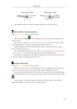
Page 11: ... Aileron When rolling the plane to right aileron shall produce a left compensation automatically make plane go back horizontal On the contrary when rolling to left aileron will produce a right compensation Please see as below If the compensation direction is not correct please move the Dip switch 1 to the other side 2 Elevator When pitching up the plane elevator shall produce a down compensation a...

Page 12: ...me angle of last position before out of signal Within radio range please switch to Balance Mode and land Please keep an eye on the quantity of GPS signal and voltage value fly carefully Please note if the quantity of satellite is less than 7 the positioning might not be correct 8Fail Safe to RTH mode Fail Safe is a receiver s function to preset position when receiver is out of signal Some receiver...

Page 13: ...sition Set CTL Parameters Set CTL Parameters Set RTH Parameters Set RTH Return to Home Parameters Set OSD Parameters Set OSD Interface Flight Parameters Reverse and delta wing mixing Fence Area Set Set Fence Mode Area Way Point Set1 Set Way Point Mode1 Way Point Set2 Set Way Point Mode2 Flight Record Records of flight time curding range power consumption and every highest record RECENT refers to t...

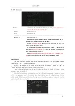
Page 14: ...k to left or right side within 3 seconds after power on can also enter neutral point check Launch Assist After turning the function on ON Launch Assist function which can help to control throttle and reduce the difficulty of take off in manual throwing process Switch to balance mode and the throttle will not be started OSD displays T throttle s volume and Launch tip as is shown below which means l...

Page 15: ...shows Aileron and elevator can also be controlled through CH1 and CH2 OFF Turn off the mode Set RTH Parameters Max Roll Max roll angle while return to home 20 to 40 degree recommended Max UP Max pitch up angle while return to home 20 to 40 degree recommended Max Down Max pitch down angle while return to home 20 to 35 degree recommended Elevate Angle Level flight s elevate angle 3 to 15 degree reco...

Page 16: ...Normal interface Fighter HUD interface ALL Info Show all attitude information P or N Xin PAL NTSC selection Show Current Current Value Display Cur Calibrat Current calibration The rheometer will adjust and input the correct power consumption after landing to calibrate the displayed battery capacity MAH Unit F Foot and m Meter Unit Selection LowPowerAlarm Low Voltage Alarm Option There will be a fl...

Page 17: ...ontrol by adjusting Dip Switch 4 Fence Area Set Switching to CH5 50 and 30 CH6 70 within rectangle area and above safe height it is Balance Mode otherwise it switches to RTH mode Fence Mode Fence Mode ON or OFF North Dist North Distance m East Dist East Distance m South Dist South Distance m West Dist West Distance m Safe Height Set Height m ...

Page 18: ...orth distance away from Home m means South and means North Height Waypoint 1 Height m WP2 WP 2 On Off Lng Dist Waypoint 2 East West distance away from Home m means East and means West Lat Dist Waypoint 2 South North distance away from Home m means South and means North Height Waypoint 2 Height m WP3 WP 3 On Off Lng Dist Waypoint 3 East West distance away from Home m means East and means West Lat D...

Page 19: ... good enough drift even stick back to center and decrease it when the plane swings 2 If plane pitches up or down when stick back to center please adjust the elevate angle value Do not adjust through SUB TRIM otherwise RTH Mode won t be precise Adjusting Return to Home Mode 1 Switch to RTH Mode Important parameters Home Direction Roll Angle Pitch Angle and RTH Throttle shown on OSD shall be checked...

Page 20: ...device some USB AV card output is incomplete Q OSD disappear once plugged the camera A Change PAL NTSC option use mainstream FPV specialized camera some surveillance camera is compatible Q Cannot locate home displaying Waiting GPS Home A Seeing OSD Waiting GPS Home proves GPS wiring is OK otherwise please check GPS wiring GPS s white antenna shall face up keep GPS away from Video TX and Camera Som...

Page 21: ...topilot is to keep balance of flight it is not able to manipulate plane or prevent stall You must have sufficient experiences of fixed wing to control the flight 2 The autopilot is only for small scale RC model For safety concern please do not install in plane for aerial photography which might fly over crowd 3 Please install the autopilot depends on your demands and check the condition before fly...

Reviews: