background image


Step 2: Choose your Video Frequency


The 5.8 G 0.5w 40CH transmitter has a dip-switch. The frequency is as per: 


0, 1 indicates the position of the switch, X indicates the switch can be located in any position. 

Frequency 

CS3 

CS2 

CS1 

S3 

S2 

S1 

Frequency 

CS3 

CS2 

CS1 

S3 

S2 

S1 

Frequency 

CS3 

CS2 

CS1 

S3 

S2 

S1 

5740 

5865 

5705 

5760 

5845 

5685 

5780 

5825 

5665 

5800 

5805 

5645 

5820 

5785 

5885 

5840 

5765 

5905 

5860 

5745 

5925 

5880 

5725 

5945 

5733 

5658 


5752 

5695 


5771 

5732 


5790 

5769 


5809 

5806 


5828 

5843 


5847 

5880 


5866 

5917 


Step 3: Powered on test 


1)


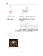
Install antenna 5.8G to transmitter; 


2)


Get the battery; 


Summary of Contents for Hummingbird

Page 1: ...nce of adults and please carefully read the user manual or under guidance of an experienced person if you are a new user 4 Please plug off the GPS to configure the airplane before using it for the first time 5 Please ensure there is no child or any viewers while configure the airplane otherwise it may hurt others 6 Please keep the airplane stored in dry and ventilated place if it is not used for a...

Page 2: ...p 3 Powered on test 6 Step 4 Prepare PWM of 433 UHF 7 Step 5 Final check 9 3 Testing the airplane 9 Step 1 Preparation 9 Step 2 Requirement of radio 9 Step 3 Choose one mode 10 Step 4 Check elevens movements 10 Step 5 Further configuration 11 Step 6 Setting parameters 12 Step 7 Check radio 13 Step 8 Mechanical elevon value 13 Step 9 GPS Search 13 4 User Instruction 14 ...

Page 3: ...atching with Arkbird 5 8G directional panel antenna or Arkbird mini AAT the transmission distance can reach up to 5km The EPP material is applied to the whole body of the airplane Carbon fiber material is also added for strengthen in the process of producing It is not easy to break in a crash due to its high anti impact strength The airplane is semi finished before it is packaged ONLY a few minute...

Page 4: ...1 Propeller 5045 x 2 Servo EMAX ES08A II x2 Arkbird optimized autopilot x1 Antenna of Arkbird 5 8GHz Transmitter 500mW 40CH x1 Arkbird GPS x1 Arkbird 433UHF receiver x1 Arkbird 433UHF transmitter x1 selective The following items should be provided by the buyer Glue x1 Battery x 1 ...

Page 5: ...e hole of the fuselage see picture below c Servo lines should be connected to the ports on both sides Beware the brown line should be connected to negative port d Glue the wings to both sides of the fuselage Beware the wings should be aligned with the edge Pins or toothpicks are recommended to align them e Glue winglets Beware they should be aligned with the edge The front surface should not be gl...

Page 6: ... 1 0 0 5665 0 1 0 1 0 1 5800 0 1 1 1 1 1 5805 0 1 1 1 0 0 5645 0 1 1 1 0 1 5820 1 0 0 1 1 1 5785 1 0 0 1 0 0 5885 1 0 0 1 0 1 5840 1 0 1 1 1 1 5765 1 0 1 1 0 0 5905 1 0 1 1 0 1 5860 1 1 0 1 1 1 5745 1 1 0 1 0 0 5925 1 1 0 1 0 1 5880 1 1 1 1 1 1 5725 1 1 1 1 0 0 5945 1 1 1 1 0 1 5733 0 0 0 1 1 0 5658 0 0 0 0 X X 5752 0 0 1 1 1 0 5695 0 0 1 0 X X 5771 0 1 0 1 1 0 5732 0 1 0 0 X X 5790 0 1 1 1 1 0 57...

Page 7: ...ting the monitor and receiver Upon they are connected the OSD will display following parameters If GPS has been installed the motor will slowly beep every 1 second Or if the GPS has not been installed the OSD will display parameters as follows Please ensure that all data about monitor autopilot transmitter and 433 receiver is reasonably correct Then power off the airplane Step 4 Prepare PWM of 433...

Page 8: ...down pitch 3 CH3 For throttle motor 4 CH4 For direction track 5 CH5 For switches of 2 3 control flaps excluding CH1 CH4 6 CH6 For switches of 3 control flaps excluding CH1 CH5 4 Please make sure that each part is connected correctly before powering on If the 433 transmitter works well the LED yellow will flash fast If the 433 transmitter does not receive signal from receiver of radio the same ligh...

Page 9: ...earch for satellites which may cause failure of entering OSD All operations hereunder are done without GPS It could be located as per the photo below Step 2 Requirement of radio The functions of radio are varied from different brands Please refer to relevant instructions on your radio s manual 1 Number of total channels should be equal to or over 6 2 Create a new model on your radio 3 No mix mode ...

Page 10: ...red square stands for Balance Mode c The flag in the red square stands for Return to Home Mode Step 4 Check elevons movements Keep the airplane in Balance Mode the icon will be in the OSD Then the airplane should be put in front of your eyes as per the following photo the head of airplane is facing you The orientation of the elevons surface will change while it is moved up and down left and right ...

Page 11: ...ght elevon surfaces should face down as per If the orientation of elevon surface is not right please note it and change negative and positive value of pitch in OSD Step 5 Further configuration After completion of Step 4 Set the switches so Manual Mode should be the flight mode and throttle value should be the lowest Then move your aileron stick to the rightmost or leftmost Don t touch anything els...

Page 12: ...o be moved down to FLIGHT MIX GIMBAL see photo at the left then rocker of aileron roll needs to be moved to right The parameter of ROLL needs to be accordingly changed if orientation of elevon surface is wrong as aforesaid test To turn NORM to INVERS or INVERS to NORM the stick for roll needs to be moved right and the stick for pitch needs to be moved down The way to adjust the parameter of going ...

Page 13: ...stant controller should be reset to zero Please ensure the back edge of elevon surface is aligned with the back edge of airplane otherwise the position needs to be adjusted by moving the elevon plate Step 9 GPS Search 1 When all aforesaid steps are done GPS can be plugged in back again to the autopilot Then the cabin can be closed with all lines correctly connected 2 Upon the airplane is powered o...

Page 14: ...roll and pitch value 12 The reference of current altitude relate to HOME 13 The reference of control value The dotted lines indicate horizon It is like the ground showed in the eyes of a person in the airplane The relative location between the airplane and HOME can be defined in the map of the central part It is subject to absolute coordinate system in which upside indicates North and right side i...

Page 15: ...e should automatically turn to be Return Home Mode as displayed in OSD If this process cannot done within 5 seconds it may be caused by failure of lost control protection Both radio and transmitter need to be reset 2 The default mode should be Balance Mode Upon powering off the radio the mode should automatically turn to be Return Home Mode as displayed in OSD If this process cannot be done within...

Page 16: ...ius of the HOME the throttle will not start unless the airplane is in Manual Mode Steps 1 Turn the mode to be Balance Mode 2 Accelerate the throttle to the highest level 3 Hold the airplane in hand and run a few meters 4 Wait the throttle automatically starts 5 Horizontally throw the airplane into air when the throttle is on 6 The airplane will automatically climb up 7 The airplane will be under c...

Reviews: