IMPORTANT NOTES:
• All wiring must be done in accordance with the NEC, and State and Local Codes.
• This product is not designed to be an extension of a structure’s hard wiring.
• Arlington recommends using a qualified electrician to install line voltage wiring and devices.
COMPONENTS ARE NOT ENERGIZED UNTIL THE FLEXIBLE CORD IS PLUGGED INTO AN EXISTING
WALL RECEPTACLE. FOLLOW ALL INSTRUCTIONS: DO NOT PLUG IN THE FLEXIBLE CORD UNTIL ALL
OTHER WIRING IS COMPLETE.
If you have questions or if parts are missing, please call our Customer Service Department at 1-800-233-4717.
Do not call or return this product to your local store or distributor.
Arlington Industries, Inc.
Scranton, PA 18517 • 800.233.4717
FAX 570.562.0646 • www.aifittings.com
Email: sales@aifittings.com
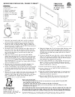
INSTALLATION INSTRUCTIONS – TV BRIDGE™ KIT
TVBR2505K
TVBR2505KGC
(W/ GROUND CLIP)
1
Locate position of television and install TV mounting bracket
per bracket manufacturer's instructions.
2
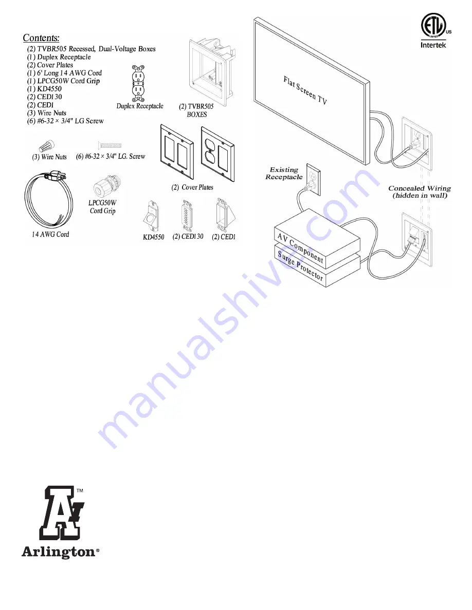
Locate upper TVBR505 box behind TV installation, avoiding
mounting bracket. Determine location of wall studs and position
TVBR505 away from studs or other obstructions inside the wall.
3
Locate position of lower TVBR505 in same stud bay as upper
box location. Locate lower box ensuring supplied cord will
reach an existing receptacle or surge protector (optional) to
power the installation.
4
Cut hole in wall for both TVBR505 boxes. Pull 14/2 with ground,
UL listed non-metallic sheathed cable, leaving enough cable to
easily complete the installation Use only copper wiring for this
installation. Pull low-voltage, coaxial, speaker wires etc. now,
before the TVBR505 boxes are installed in the wall.
5
Strip approx. 6 inches of sheathing from NM cable and strip ½"
of insulation from conductors on both ends of NM cable.
6
Install NM cable into TVBR505 line-voltage box using cable
connectors (provided) and secure TVBR505 into wall open-
ings by tightening two wing screws visible on the flange.
7
Wire duplex receptacle to upper end of NM cable and install
receptacle into power side of Upper TVBR505 box. Attach black
(hot) conductor to brass colored screw, white (neutral) conduct-
or to silver colored screw, ground conductor to green screw
(on receptacle).
8
Strip ½" length of insulation from supplied 14 AWG flexible
cord. Remove cord grip nut and install cord into LPCG50W
cord grip. Install LPCG50W w/ cord into KD4550 using
supplied locknut to secure the assembly.
9
Using supplied wire nuts, connect cord conductors to
corresponding conductors (white to white, black to black,
green to ground) of NM cable already installed in lower
TVBR505 box. Firmly tighten wire nuts.
10
Install KD4550 assembly to lower TVBR505 box using
supplied #6 screws. Mount CED130 or CED1 to low-voltage
sides of upper & lower TVBR505 boxes using supplied #6
screws.
11
Install cover plates using screws provided.
12
Install television to mounting bracket in accordance with
manufacturer's instructions.
13
Connect TV power cable to installed duplex outlet in upper
TVBR505 and make necessary low-voltage connections.
14
Energize TVBR2505K by plugging the installed flexible cord
into an existing receptacle or surge protector.
C


