Bus Interface Unit
ARM DDI 0186A
Copyright © 2000 ARM Limited. All rights reserved.
6-3
6.2
Write buffer operation
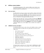
The ARM966E-S implements a 12-entry write buffer, where the entries can be address
or data depending on the nature of the writes being executed by the ARM9E-S core. The
write buffer helps to decouple the core from the wait cycles incurred when accessing the
AHB. If a write is sent to the write buffer, the core is able to continue program execution
without having to wait for the write to complete on the AHB. More writes can be
committed to the write buffer without stalling if spare entries are available.
If the write buffer becomes full, the ARM9E-S core must be stalled until an AHB access
occurs and some write data is written, therefore freeing up the necessary FIFO entries.
Alternatively, if the core performs a read from or unbuffered write to the AHB address
space, the core is stalled until all write buffer entries have been written (the write buffer
is
drained
). The write buffer is drained to ensure data coherency, in that the core might
try to read from a location that it has recently modified and is still in the write buffer
awaiting AHB access.
6.2.1
Committing write data to the write buffer
The write buffer is used when the following conditions are met:
•
the write buffer is enabled
•
the address is in a bufferable region
•
the address is in AHB external memory, or the address selects a tightly-coupled
SRAM that is disabled.
For details on write buffer enable and the ARM966E-S fixed address map, see
•
•
About the ARM966E-S memory map
When a write is performed by the core and conforms to the above conditions, the
address for the write is put into the first available entry of the write buffer FIFO. The
next available entry is used for the write data. If the write is a store multiple (
STM
),
subsequent entries are used for each word of the
STM
. It is therefore possible for the FIFO
to contain 11 words of a
STM
where the first entry contains the address and the remaining
11 entries contain the write data.
Alternatively, if several shorter bufferable
STM
or single writes (
STR
) instructions are
performed, one address entry is used for each write instruction. The worst case is that
only six data words fill the FIFO caused by six
STR
writes. In this case the FIFO holds
six address entries and six data entries.
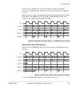
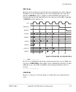
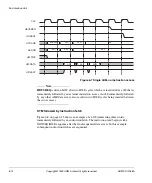
Figure 6-1 on page 6-4 shows an example where the BIU FIFO is being filled by the
following write instructions:
Summary of Contents for ARM966E-S
Page 6: ...Contents vi Copyright 2000 ARM Limited All rights reserved ARM DDI 0186A ...
Page 20: ...Introduction 1 4 Copyright 2000 ARM Limited All rights reserved ARM DDI 0186A ...
Page 48: ...Tightly coupled SRAM 4 12 Copyright 2000 ARM Limited All rights reserved ARM DDI 0186A ...
Page 80: ...Bus Interface Unit 6 20 Copyright 2000 ARM Limited All rights reserved ARM DDI 0186A ...
Page 118: ...Debug Support 8 26 Copyright 2000 ARM Limited All rights reserved ARM DDI 0186A ...
Page 130: ...Test Support 10 8 Copyright 2000 ARM Limited All rights reserved ARM DDI 0186A ...
Page 142: ...Instruction cycle timings 11 12 Copyright 2000 ARM Limited All rights reserved ARM DDI 0186A ...
Page 158: ...Signal Descriptions A 16 Copyright 2000 ARM Limited All rights reserved ARM DDI 0186A ...
Page 176: ...AC Parameters B 18 Copyright 2000 ARM Limited All rights reserved ARM DDI 0186A ...

