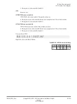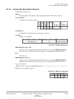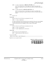
B1.42
CPU Auxiliary Control Register
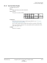
The CPUACTLR characteristics are:
Purpose
Provides
IMPLEMENTATION DEFINED
configuration and control options for the processor. There is
one 64-bit CPU Auxiliary Control Register for each core in the processor.
Usage constraints
This register is accessible as follows:
EL0
(NS)
EL0
(S)
EL1
(NS)
EL1
(S)
EL2 EL3
(SCR.NS = 1)
EL3
(SCR.NS = 0)
-
-
RW
RW RW RW
RW
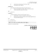
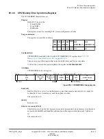
The CPU Auxiliary Control Register can be written only when the system is idle. Arm
recommends that you write to this register after a powerup reset, before the MMU is enabled,
and before any master interface or ACP traffic begins.
Setting many of these bits can cause significantly lower performance on your code. Therefore, it
is suggested that you do not modify this register unless directed by Arm.
Configurations
CPUACTLR is:
• Common to the Secure and Non-secure states.
• Mapped to the AArch64 CPUACTLR_EL1 register. See
Attributes
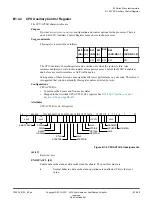
CPUACTLR is a 64-bit register.
31
22
18 17
0
9
10
11
12
13
15
16
19
20
21
28
29
RES
0
DIDIS
RES
0
L1PCTL
L1RADIS
RADIS
NPFSTRM
DSTDIS
STRIDE
63
CDIDIS
30
23
24
STBPFDIS
STBPFRS
27 26 25
DTAH
RES
0
ENDCCASCI
45 44 43
7
RES
0
6 5
DODMBS
L1DEIEN
RES
0
RES
0
DYNSDIS
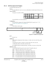
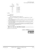
Figure B1-6 CPUACTLR bit assignments
[63:45]
Reserved,
RES0
.
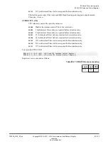
ENDCCASCI, [44]
Enable data cache clean as data cache clean/invalidate. The possible values are:
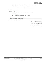
0
Normal behavior, data cache clean operations are unaffected. This is the reset
value.
B1 AArch32 system registers
B1.42 CPU Auxiliary Control Register
100236_0100_00_en
Copyright © 2015–2017, 2019 Arm Limited or its affiliates. All rights
reserved.
B1-208
Non-Confidential
Summary of Contents for Cortex-A35
Page 4: ......
Page 18: ......
Page 26: ......
Page 27: ...Part A Functional Description ...
Page 28: ......
Page 145: ...Part B Register Descriptions ...
Page 146: ......
Page 573: ...Part C Debug ...
Page 574: ......
Page 845: ...Part D Appendices ...
Page 846: ......

