A.1
About the signal descriptions
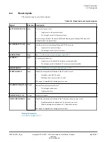
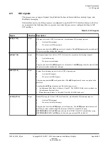
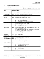
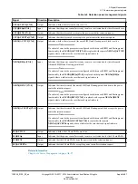
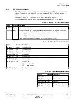
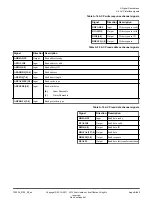
The tables in this appendix provide direction information and high-level descriptions about the signals at
the external interfaces of the processor.
Some of the buses include a configurable width field, <Signal>[CN:0], where CN = 0, 1, 2, or 3, to
encode up to four cores. For example:
•
nIRQ[0]
represents a core 0 interrupt request.
•
nIRQ[2]
represents a core 2 interrupt request.
Some signals are specified in the form
<signal>x
where x = 0, 1, 2 or 3 to reference core 0, core 1, core
2, core 3. If a core is not present, the corresponding pin is removed. For example:
•
PMUEVENT0[29:0]
represents the core 0 PMU event bus.
•
PMUEVENT3[29:0]
represents the core 3 PMU event bus.
The number of signals changes depending on the configuration. For example, the CHI interface signals
are not present when the processor is configured to have an ACE memory interface.
A Signal Descriptions
A.1 About the signal descriptions
100236_0100_00_en
Copyright © 2015–2017, 2019 Arm Limited or its affiliates. All rights
reserved.
Appx-A-848
Non-Confidential
Summary of Contents for Cortex-A35
Page 4: ......
Page 18: ......
Page 26: ......
Page 27: ...Part A Functional Description ...
Page 28: ......
Page 145: ...Part B Register Descriptions ...
Page 146: ......
Page 573: ...Part C Debug ...
Page 574: ......
Page 845: ...Part D Appendices ...
Page 846: ......

