A.4
Reset signals
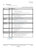
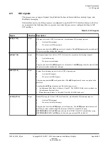
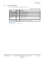
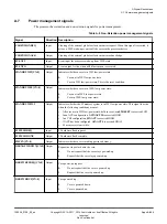
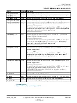
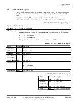
The processor uses a set of reset signals.
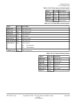
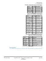
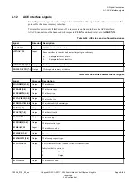
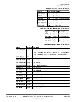
Table A-3 Reset and reset control signals
Signal
Direction Description
nCPUPORESET[CN:0]
Input
Processor powerup reset:
0
Apply reset to all processor logic.
1
Do not apply reset to all processor logic.
Processor logic includes Advanced SIMD and floating-point, debug, ETM trace unit,
breakpoint and watchpoint logic.
nCORERESET[CN:0]
Input
Individual core resets excluding debug and ETM trace unit:
0
Apply reset to processor logic.
1
Do not apply reset to processor logic.
nPRESETDBG
Input
See
.
nL2RESET
Input
L2 memory system reset:
0
Apply reset to the shared L2 memory system controller.
1
Do not apply reset to the shared L2 memory system controller.
nMBISTRESET
Input
See
L2RSTDISABLE
Input
Disable the automatic invalidation of the L2 cache at reset:
0
Hardware resets the L2 cache.
1
Hardware does not reset the L2 cache.
This signal is sampled only during processor reset.
WARMRSTREQ[CN:0]
Output
Request for a processor warm reset:
0
Do not apply warm reset.
1
Apply warm reset.
DBGRSTREQ[CN:0]
Output
Warm reset request.
DBGL1RSTDISABLE
Input
Disable the automatic invalidation of the L1 data cache at processor reset:
0
Enable automatic invalidation of L1 data cache on reset.
1
Disable automatic invalidation of L1 data cache on reset.
This signal is sampled only during processor reset.
Related information
A3.3 Resets
A Signal Descriptions
A.4 Reset signals
100236_0100_00_en
Copyright © 2015–2017, 2019 Arm Limited or its affiliates. All rights
reserved.
Appx-A-851
Non-Confidential
Summary of Contents for Cortex-A35
Page 4: ......
Page 18: ......
Page 26: ......
Page 27: ...Part A Functional Description ...
Page 28: ......
Page 145: ...Part B Register Descriptions ...
Page 146: ......
Page 573: ...Part C Debug ...
Page 574: ......
Page 845: ...Part D Appendices ...
Page 846: ......

