D1.1
AArch32 debug register summary
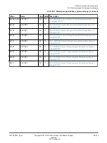
The following table summarizes the 32-bit and 64-bit debug control registers that are accessible in the
AArch32 Execution state from the internal CP14 interface. These registers are accessed by the
MCR
and
MRC
instructions in the order of CRn, op2, CRm, Op1 or
MCRR
and
MRRC
instructions in the order of CRm,
Op1.
For those registers not described in this chapter, see the
Arm
®
Architecture Reference Manual Arm
®
v8, for
Arm
®
v8-A architecture profile
.
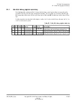
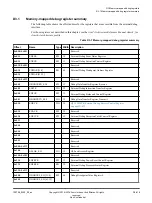
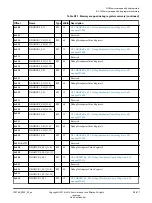
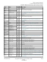
Table D1-1 AArch32 debug register summary
CRn Op2 CRm Op1 Name
Type Reset
Description
c0
0
c1
0
DBGDSCRint
RO
000x0000
Debug Status and Control Register, Internal View
c0
0
c5
0
DBGDTRTXint WO
-
Debug Data Transfer Register, Transmit, Internal View
c0
0
c5
0
DBGDTRRXint RO
0x00000000
Debug Data Transfer Register, Receive, Internal View
D1 AArch32 debug registers
D1.1 AArch32 debug register summary
100798_0300_00_en
Copyright © 2016–2018 Arm Limited or its affiliates. All rights
reserved.
D1-404
Non-Confidential
Summary of Contents for Cortex-A76 Core
Page 4: ......
Page 22: ......
Page 23: ...Part A Functional description ...
Page 24: ......
Page 119: ...Part B Register descriptions ...
Page 120: ......
Page 363: ...Part C Debug descriptions ...
Page 364: ......
Page 401: ...Part D Debug registers ...
Page 402: ......
Page 589: ...Part E Appendices ...
Page 590: ......


