A4.4
Architectural clock gating modes
When the Cortex-A76 core is in standby mode, it is architecturally clock gated at the top of the clock
tree.
Wait for Interrupt
(WFI) and
Wait for Event
(WFE) are features of Armv8-A architecture that put the
core in a low-power standby mode by architecturally disabling the clock at the top of the clock tree. The
core is fully powered and retains all the state in standby mode.
A4.4.1
Core Wait for Interrupt
WFI puts the core in a low-power state by disabling most of the clocks in the core, while keeping the
core powered up.
There is a small dynamic power overhead from the logic that is required to wake up the core from WFI
low-power state. Other than this, the power that is drawn is reduced to static leakage current only.
When the core executes the
WFI
instruction, the core waits for all instructions in the core to retire before
it enters low-power state. The
WFI
instruction ensures that all explicit memory accesses that occurred
before the
WFI
instruction in program order have retired.
In addition, the
WFI
instruction ensures that store instructions have updated the cache or have been issued
to the L3 memory system.
While the core is in WFI low-power state, the clocks in the core are temporarily enabled without causing
the core to exit WFI low-power state when any of the following events are detected:
• An L3 snoop request that must be serviced by the core data caches.
• A cache or TLB maintenance operation that must be serviced by the core L1 instruction cache, data
cache, TLB, or L2 cache.
• An APB access to the debug or trace registers residing in the core power domain.
• A GIC CPU access through the AXI4 stream channel.
Exit from WFI low-power state occurs when one of the following occurs:
• The core detects one of the WFI wake-up events.
• The core detects a reset.
For more information, see the
Arm
®
Architecture Reference Manual Armv8, for Armv8-A architecture
profile
.
A4.4.2
Core Wait for Event
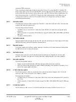
WFE is a feature of the Armv8-A architecture. It uses a locking mechanism based on events, to put the
core in a low-power state by disabling most of the clocks in the core, while keeping the core powered up.
There is a small dynamic power overhead from the logic that is required to wake up the core from WFE
low-power state. Other than this, the power that is drawn is reduced to static leakage current only.
A core enters into WFE low-power state by executing the
WFE
instruction. When the
WFE
instruction
executes, the core waits for all instructions in the core to complete before it enters the idle or low-power
state.
If the event register is set, execution of WFE does not cause entry into standby state, but clears the event
register.
While the core is in WFE low-power state, the clocks in the core are temporarily enabled without causing
the core to exit WFE low-power state when any of the following events are detected:
• An external snoop request that must be serviced by the core data caches.
• A cache or TLB maintenance operation that must be serviced by the core L1 instruction cache, data
cache, TLB, or L2 cache.
• An APB access to the debug or trace registers residing in the core power domain.
• A GIC CPU access through the AXI4 stream channel.
A4 Power management
A4.4 Architectural clock gating modes
100798_0300_00_en
Copyright © 2016–2018 Arm Limited or its affiliates. All rights
reserved.
A4-50
Non-Confidential
Summary of Contents for Cortex-A76 Core
Page 4: ......
Page 22: ......
Page 23: ...Part A Functional description ...
Page 24: ......
Page 119: ...Part B Register descriptions ...
Page 120: ......
Page 363: ...Part C Debug descriptions ...
Page 364: ......
Page 401: ...Part D Debug registers ...
Page 402: ......
Page 589: ...Part E Appendices ...
Page 590: ......

