Nested Vectored Interrupt Controller
ARM DDI 0337G
Copyright © 2005-2008 ARM Limited. All rights reserved.
8-13
Unrestricted Access
Non-Confidential
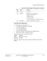
Interrupt Set-Enable Registers
Use the Interrupt Set-Enable Registers to:
•
enable interrupts
•
determine which interrupts are currently enabled.
Each bit in the register corresponds to one of 32 interrupts. Setting a bit in the Interrupt
Set-Enable Register enables the corresponding interrupt.
When the enable bit of a pending interrupt is set, the processor activates the interrupt
based on its priority. When the enable bit is clear, asserting its interrupt signal pends the
interrupt, but it is not possible to activate the interrupt, regardless of its priority.
Therefore, a disabled interrupt can serve as a latched general-purpose I/O bit. You can
read it and clear it without invoking an interrupt.
Clear an Interrupt Set-Enable Register bit by writing a 1 to the corresponding bit in the
Interrupt Clear-Enable Register (see
Interrupt Clear-Enable Registers
on page 8-14).
Note
Clearing an Interrupt Set-Enable Register bit does not affect currently active interrupts.
It only prevents new activations.
The register address, access type, and Reset state are:
Address
0xE000E100-0xE000E11C
Access
Read/write
Reset state
0x00000000
[30]
SKEW
1 = the calibration value is not exactly 10ms because of clock frequency. This could affect its
suitability as a software real time clock.
[29:24]
-
Reserved
[23:0]
TENMS
This value is the Reload value to use for 10ms timing. Depending on the value of SKEW, this might
be exactly 10ms or might be the closest value.
If this reads as 0, then the calibration value is not known. This is probably because the reference
clock is an unknown input from the system or scalable dynamically.
Table 8-7 SysTick Calibration Value Register bit assignments (continued)
Bits
Field
Function


