Debug
ARM DDI 0363E
Copyright © 2009 ARM Limited. All rights reserved.
11-10
ID013010
Non-Confidential, Unrestricted Access
11.4
Debug register descriptions
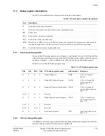
Table 11-5 shows definitions of terms used in the register descriptions.
11.4.1
Accessing debug registers
To access the CP14 debug registers you set Opcode_1 and Opcode_2 to zero. The CRn and CRm
fields of the coprocessor instructions encode the CP14 debug register number, where the register
number is
{<Opcode2>, <CRm>}
. In addition, the CRn field can specify additional registers.
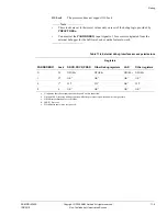
Table 11-6 shows the CP14 debug register map.
11.4.2
CP14 c0, Debug ID Register
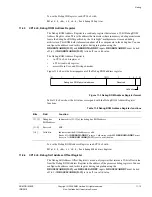
The DIDR is a read-only register that identifies the debug architecture version and specifies the
number of debug resources that the processor implements.
Table 11-5 Terms used in register descriptions
Term
Description
R
Read-only. Written values are ignored.
W
Write-only. This bit cannot be read. Reads return an Unpredictable value.
RW
Read or write.
RAZ
Read-As-Zero. Always zero when read.
RAO
Read-As-One. Always one when read.
SBZP
Should-Be-Zero
(SBZ) or
Preserved
(P). Must be written as 0 or preserved by writing the same value previously
read from the same fields on the same processor. These bits are usually reserved for future expansion.
UNP
A read from this bit returns an Unpredictable value.
Table 11-6 CP14 debug register map
CRn
Op1
CRm
Op2
CP14 debug register name
Abbreviation
Reference
c0
0
c0
0
Debug ID Register
DIDR
CP14 c0, Debug ID
Register
c1
0
c0
0
Debug ROM Address Register
DRAR
CP14 c0, Debug ROM
Address Register
on
page 11-12
c2
0
c0
0
Debug Self Address Offset Register
DSAR
CP14 c0, Debug Self
Address Offset Register
on
page 11-12
c3-c15
0
c0
0
Reserved
-
-
c0
0
c1
0
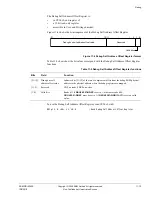
Debug Status and Control Register
DSCR
CP14 c1, Debug Status
and Control Register
on
page 11-14
c1-c15
0
c1
0
Reserved
-
-
c0-c15
0
c2-c4
0
Reserved
-
-
c0
0
c5
0
Data Transfer Register
DTR
Data Transfer Register
on
page 11-18


