2.1
Target connector selection guide
When choosing a debug or trace connector to design into a target board, there are many connector
attributes to consider.
The connector attributes are:
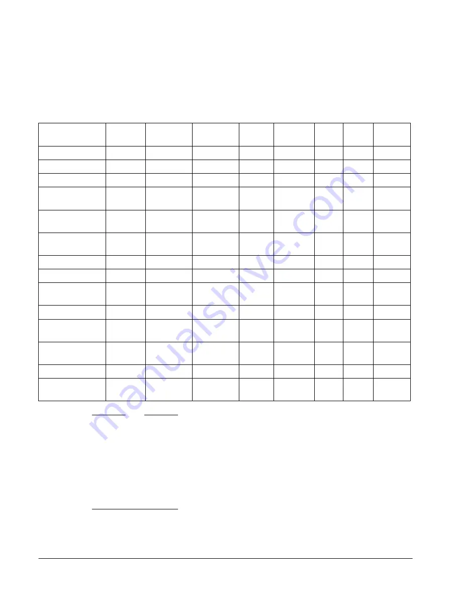
Table 2-1 Connector attributes
Connector
Arm JTAG
20
CoreSight 10 CoreSight 20 TI JTAG
14
MICTOR 38 MIPI 34 MIPI 60 HSSTP 40
JTAG supported
Yes
Yes
Yes
Yes
Yes
Yes
Yes
Yes
SWD supported
Yes
Yes
Yes
Yes
Yes
Yes
Yes
Yes
SWO trace supported
Yes
Yes
Yes
Yes
Yes
Yes
Yes
Yes
Parallel trace
supported
No
No
Yes
No
Yes
Yes
Yes
No
Max parallel trace
width (1)
N/A
N/A
4
N/A
16
4
32
N/A
Separate debug/trace
voltage domains
No
No
No
No
Yes
Yes
Yes
N/A
Requires adapter
No
No
No
Yes
Yes
Yes
Yes
No
Cable signal integrity
Medium
Good
Good
Poor
Excellent
Good
Excellent Excellent
MIPI pinout
compatible
No
Yes
Yes
No
No
Yes
Yes
No
Target connector cost
Low
Low
Low
Low
High
Low
Medium
Medium
Connector durability
(2)
High
Low
Low
High
Medium
Low
Medium
Medium
Approximate footprint
area (mm²) (3)
297
65
95
250
221
140
170
170
Through-hole/SMD
Either
Either
Either
Either
SMD (4)
Either
SMD
SMD (5)
Ease of assembly
(placement/soldering)
High
High
High
High
Low
High
Medium
Medium
Note
1. The trace width supported by the connector. DSTREAM-ST supports up to 4-bit wide parallel trace.
2. Through-hole variants of connectors are more durable than SMD variants.
3. Assumes an SMD part is used. Through-hole parts use additional space on the opposite side of the
board.
4. The Mictor 38 connector is a hybrid part that has SMD signal pins and through-hole ground pins. The
ground pins must be solder-pasted from the component side. Mictor 38 connector is not
recommended for future designs.
5. The HSSTP 40-way connector has locking pins which must be solder-pasted from the component
side.
2 Target interface connectors
2.1 Target connector selection guide
101761_0100_01_en
Copyright © 2019 Arm Limited or its affiliates. All rights reserved.
2-34
Non-Confidential

