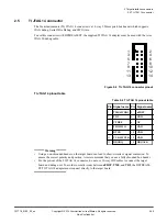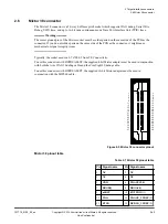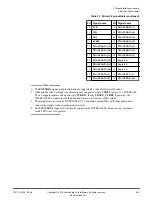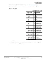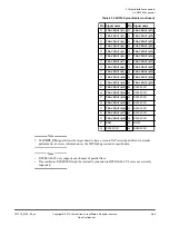
Table 2-4 Arm CoreSight 20 pinout table (DSTREAMCS20=0) (continued)
Pin Signal name Pin Signal name
7
Key (
NC
)
8
TDI
9
GND
10
nSRST
11
GND
(1)
12
TRACECLK
13
GND
(1)
14
TRACEDATA[0]
15
GND
16
TRACEDATA[1]
17
GND
18
TRACEDATA[2]
19
GND
20
TRACEDATA[3]
Pinout when
DSTREAMCS20
is set to
1
:
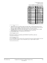
Table 2-5 Arm CoreSight 20 pinout table (DSTREAMCS20=1)
Pin Signal name Pin Signal name
1
VTREF
2
TMS
/
SWDIO
3
GND
4
TCK
/
SWCLK
5
GND
6
TDO
/
SWO
7
Key (
NC
)
8
TDI
9
GND
10
nSRST
11
GND
(1)
12
RTCK
13
GND
(1)
14
SWO
15
GND
16
nTRST
17
GND
18
DBGRQ
19
GND
20
DBGACK
1. Although these pins are typically grounded on the target board, the MIPI specification also allows
them to carry power. If they are connected to a power rail (or rails) on the target board, these pins
must also be AC-coupled to
GND
. To couple the pins to
GND
, use 100nF capacitors that are close to
the connector.
Note
Pin 7 must be removed for compatibility with DSTREAM-ST and MIPI specifications.
Warning
Using a non-shrouded header on the target board can lead to short-circuits or signal contention. To ensure
the correct polarity and position, Arm recommends that you use a fully shrouded box header.
2 Target interface connectors
2.4 CoreSight
™
20 connector
101714_0100_02_en
Copyright © 2019 Arm Limited or its affiliates. All rights reserved.
2-38
Non-Confidential

