Target
Device
Debug
Connector
Auxiliary
Circuitry
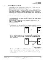
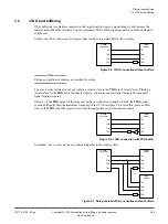
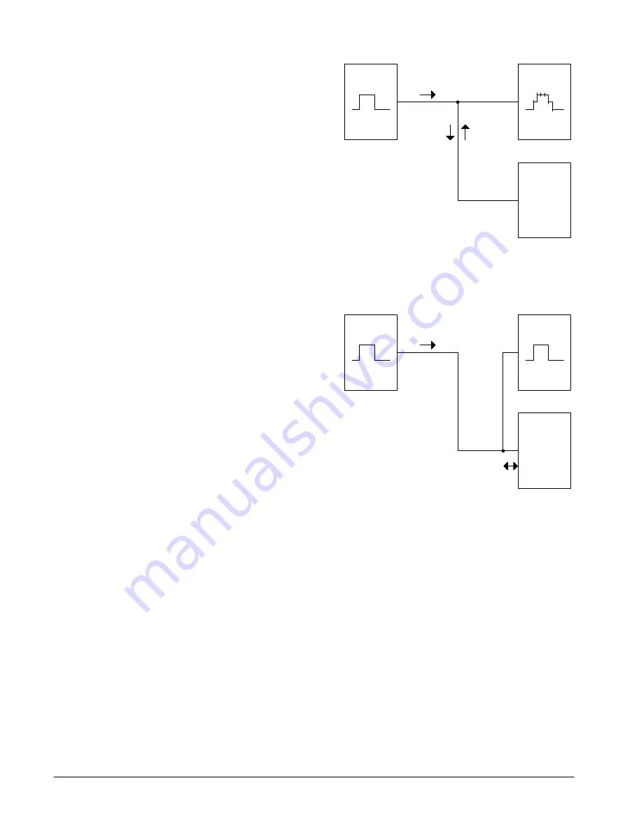
Figure 3-3 Long stub causing false edges
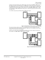
The simplest method to avoid a long stub causing false edges is to shorten the stub length by
rerouting the signal. While rerouting the signal might add length to the signal route, the reduction in
stub length is much more favorable.
Target
Device
Debug
Connector
Auxiliary
Circuitry
Reduced
Stub
Figure 3-4 Improved route with shorter stub
Alternative methods include:
— To prevent signal reflections affecting the incoming signal, use a buffer at T-junctions. This
method is used to replicate clock signals.
— To route a signal without stubs, use an analog switch. This method is used when a device pin has
multiple functions, for example, JTAG and general I/O.
— To deflect a larger portion of the signal away from the stub, use a resistor at the junction of the
stub. This method is used when the stub leads to lower-bandwidth circuitry.
•
Ensure the continuity of return signals
As a digital signal propagates along its route, an inverse signal travels through the adjacent plane
because of the electric-field coupling between the signal and the plane. When the signal edges are
short, the return signal usually follows the path of least inductance, rather than resistance. This means
that the return signal flows through a path in the adjacent plane, that is as close as possible to the
signal route. When the return path is interrupted, it causes distortion and some loss in the signal.
3 Target board design
3.1 Overview of high-speed design
101714_0100_02_en
Copyright © 2019 Arm Limited or its affiliates. All rights reserved.
3-53
Non-Confidential

