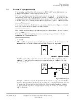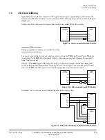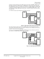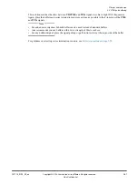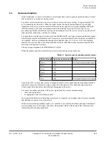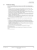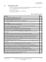
To minimize return path issues:
— Ensure that the return path that is adjacent to the signal is continuous with no slots or accidental
voids that are caused by anti-pads.
— When routing a signal from one layer to another, link the planes close to the signal via using a
return via. If the planes are at different voltages, use a low-value capacitor to AC-couple the
return path.
— When routing signals to and from a cable connector, ensure that all of the return signals of the
cable are used. Directly link the return signals or AC-couple them to ground, as necessary.
•
Minimize crosstalk
Every signal route on a target board has some effect on nearby signal tracks because of the coupling
of electric and magnetic fields between the tracks. The electric and magnetic field coupling causes
small variations in the surrounding signals which, over long enough distances, can cause data
corruption.
There are several ways to minimize electric and magnetic field coupling:
— Space the signal tracks further apart. Arm recommends to keep adjacent signals at least three
times further apart than they are from the nearest plane (the 3W rule).
— Bring the plane closer to the signals. To reduce the 3W distance that is needed between adjacent
signals, use thinner laminates between the signal and plane layers.
— Keep the signal tracks as short as possible. To cut down on routing while also reducing crosstalk,
place a debug or trace connector closer to the target device.
•
Use impedance matching
Every signal route on a target board has an effective impedance that is measured in Ohms. Effective
impedance is the equivalent resistance to ground a signal experiences when it initially enters a signal
route, before any reflection from the far end has occurred.
If the different portions of a signal route have different impedances, it can cause reflections in the
route. Reflections reduce the integrity of the signal.
DSTREAM-ST is designed to work with target boards that use 50Ω signal tracks.
Most modern PCB design tools include functionality for calculating track impedance. There are also
various free resources online for calculating the impedance of the various types of PCB track.
3 Target board design
3.1 Overview of high-speed design
101714_0100_02_en
Copyright © 2019 Arm Limited or its affiliates. All rights reserved.
3-54
Non-Confidential

