3.5
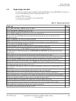
Target design checklist
To ensure your target design is compatible with the DSTREAM-ST unit or DSTREAM-PT system, your
answer to each applicable question in this checklist must be ‘Yes’.
Note
Not all questions are applicable to every target design.
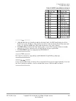
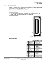
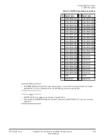
Table 3-2 Target design checklist
Check item
Status
Are any
TDI
,
TMS
,
TDO
, or
SWDIO
signals pulled
HIGH
?
Are any
TCK
,
RTCK
, or
SWCLK
signals pulled
LOW
?
Are any
nTRST
or
nSRST
signals pulled to their inactive state (usually
HIGH
)?
To pass data between the
TCK
domain and the internal clock domain, does the target device contain the necessary
synchronization logic?
If used, does
RTCK
have its own driver (separate from
TCK
)?
If
TCK
is routed to multiple devices, have you used buffers to fan-out the signal (to prevent signal reflections)?
Can the debug unit drive
nTRST
and
nSRST
separately?
To allow debug from reset, can you reset the target device without initializing its debug logic?
If using Serial wire Debug, is the
TMS
/
SWDIO
signal bidirectional (no uni-directional buffers)?
To reduce the need to calibrate during setup, are any
TRACEDATA
and
TRACECLK
signals length-matched within a
10mm window?
Where possible, have you eliminated stubs and other parasitic effects from debug and trace signals?
To obtain 50Ω output impedance, have you routed any outputs from the target device through series termination resistors?
Have the appropriate
VTREF
signal (or signals) been connected to the debug or trace connector (or connectors)?
Either directly or through a resistor of 100Ω or less, are
VTREF
pins connected to the debug/trace logic rail (or rails)?
Are the debug/trace logic rails in the range of 1.2V to 3.3V?
Are all GND pins of the debug/trace connector (or connectors) either directly connected, or AC-coupled, to GND, close to
the connector?
If using a Mictor socket, are the central GND pins solder-pasted on the same side of the board?
If using dual Mictor sockets, are the connectors positioned with the correct spacing, orientation, and alignment?
If using a standard 2.54mm or 1.27mm header, is the connector fully shrouded to avoid mis-connection (space permitting)?
If using a CoreSight 10/20 or MIPI 34 connector, have you considered the removal of pin-7?
To ensure the continuity of return paths, do any signal vias have return vias placed close to them?
Have you checked the board layout to ensure that no signals cross slots or voids in the adjacent plane (or planes)?
Where possible, has crosstalk between debug and trace signals been minimized?
Are all debug and trace signals impedance-matched to 50Ω?
3 Target board design
3.5 Target design checklist
101714_0100_02_en
Copyright © 2019 Arm Limited or its affiliates. All rights reserved.
3-60
Non-Confidential

