Timing Requirements
4-6
Copyright © 2002, 2003 ARM Limited. All rights reserved.
ARM DDI 0275D
4.3
IEEE1149.1 interface
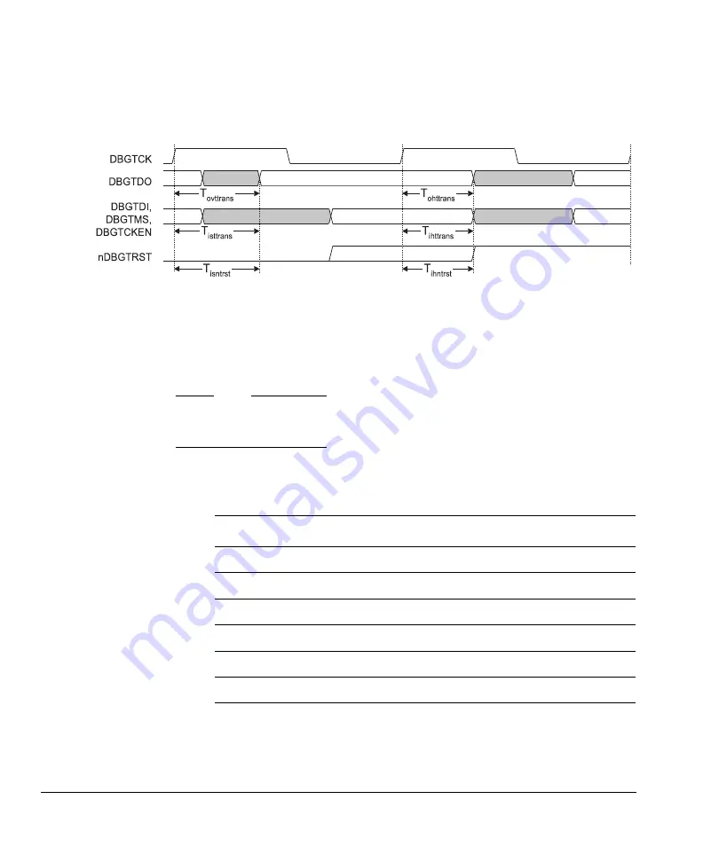
The IEEE1149.1 interface signals are shown in Figure 4-3.
Figure 4-3 IEEE1149.1 interface signals
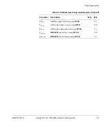
The timing requirements for the IEEE1149.1 interface trace data signals are listed in
Table 4-3. All figures are expressed as percentages of the
DBGTCK
period at
maximum operating frequency.
Note
A 0% figure in Table 4-3 indicates the hold time to clock edge plus the maximum clock
skew for internal clock buffering.
Table 4-3 IEEE1149.1 interface timing requirements
Parameter
Description
Max
Min
T
ovttrans
Rising
DBGTCK
to
DBGTDO
output valid
40%
-
T
ohttrans
DBGTDO
output hold time from
DBGTCK
rising
-
>0%
T
isttrans
JTAG inputs setup to rising
DBGTCK
-
40%
T
ihttrans
JTAG inputs hold from rising
DBGTCK
-
0%
T
isntrst
nDBGTRST
input setup to rising
DBGTCK
-
40%
T
ihntrst
nDBGTRST
input hold from rising
DBGTCK
-
0%
Summary of Contents for ETB11
Page 6: ...List of Tables vi Copyright 2002 2003 ARM Limited All rights reserved ARM DDI 0275D ...
Page 8: ...List of Figures viii Copyright 2002 2003 ARM Limited All rights reserved ARM DDI 0275D ...
Page 46: ...Functional Description 2 26 Copyright 2002 2003 ARM Limited All rights reserved ARM DDI 0275D ...
Page 70: ...Signal Descriptions A 6 Copyright 2002 2003 ARM Limited All rights reserved ARM DDI 0275D ...
Page 78: ...Glossary Glossary 4 Copyright 2002 2003 ARM Limited All rights reserved ARM DDI 0275D ...

