background image


3

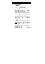
Electrical Specification: 

(

) The accuracy specification is defined as 

±

( …%reading

…count )   

At 23 

±

5

80 %RH 

ACA 

(Autorange)


Range


Resolution

Accuracy ( 50Hz~1KHz) 

Overload Protection

10A 1mA 

80A 10mA 

1.2%

±

5dgts(50~60Hz) 

2.5%

±

5dgts(60~500Hz) 

3.5%

±

10cts (500~1kHz)


80~100A 10mA 

5%

±

5dgts (50~60Hz) 

150Arms 

ACmA 

(Autorange)


Range


Resolution

Accuracy ( 50Hz~1KHz) 

Overload Protection

60mA 10uA 

600mA 100uA 

1.2%

±

5dgts(50~60Hz) 

2.5%

±

5dgts(60~500Hz) 

3.5%

±

10cts (500~1kHz) 

150Arms 

ACV 

Range


Resolution

Accuracy (50Hz~1KHz) 

Overload Protection

600V 0.1V 

1.0%

±

5cts (50~60Hz) 

1.2%

±

5cts (60~500Hz) 

2.5%

±

5cts (500~1kHz) 

660Vrms 

DCV   

Range


Resolution

Accuracy Overload 

Protection

600V 0.1V 

1%+2 

660Vrms 

Ohm ( 

Ω

 )  

Range Resolution

Accuracy

MAX Test Voltage

Overload Protection

1K

Ω

 0.1

Ω

 1%+3 

-3.3VDC 

600Vrms 

Continuity (

)  

Range 

Active Region 

MAX Test Voltage 

Overload Protection


<35 Ohm -3.3VDC  600Vrms 

Frequency HZ (Autorange) 

Function Range  Resolution

Sensitivity 

Accuracy 

A-Hz 0~100 

Hz

0.1Hz 

A-Hz 100~1K 

Hz

1Hz 


10mArms min

0.5%

±

2dgts 

V-Hz 0~100 

Hz

0.1Hz 


V-Hz 100~1K 

Hz

1Hz 


5Vrms min 

0.5%

±

2dgts 

Summary of Contents for Pro93

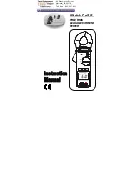
Page 1: ...Model Pro93 TRUE RMS LEAKAGE CURRENT TESTER 99 Washington Street Melrose MA 02176 Phone 781 665 1400 Toll Free 1 800 517 8431 Visit us at www TestEquipmentDepot com...

Page 2: ...ment Familiarization 4 Symbol Definition 4 Instrument Familiarization 4 Button Instruction 4 IV Measuring Instruction 6 4 1 ACA ACmA measurement 6 4 2 ACV measurement 6 4 3 DCV measurement 9 4 4 Resis...

Page 3: ...al Exercise extreme caution when measuring live systems with voltage greater than 60V DC or 30V AC Keep fingers behind the protection ring when measuring with test leads Replace batteries when the sym...

Page 4: ...y is below the proper operation range symbol will appear on the LCD display Auto Power Off The meter will power it self OFF after 10 minutes of inactivity Power Source UM 4 or AAA 1 5V battery x 2 Bat...

Page 5: ...z 3 5 10cts 500 1kHz 150Arms ACV Range Resolution Accuracy 50Hz 1KHz Overload Protection 600V 0 1V 1 0 5cts 50 60Hz 1 2 5cts 60 500Hz 2 5 5cts 500 1kHz 660Vrms DCV Range Resolution Accuracy Overload P...

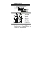
Page 6: ...ro button 11 positive input terminal 12 Battery compartment cove Button Instruction Zero Button Press Zero button to enter the Zero mode ZERO Annunciate will appear and Zero the display The reading is...

Page 7: ...seconds The meter will return to WIDE mode operation Note This meter is built with 50 60HZ function at ACA ACmA ranges How to use frequency selector button When high frequencies from such equipment a...

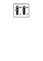
Page 8: ...urrent value is shown on the display Earth leakage current or small current that flows through a grounded wire can also be measured by this method 3 Measuring out of balance leakage current see Fig 2...

Page 9: ...7 Fig 2 Measuring out of balance leakage current 3 Phase 3 Wire system Single Phase 2 Wire system...

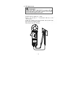
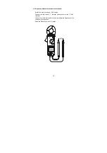
Page 10: ...this maximum to avoid Electrical shock hazard and or damage to this instrument Switch the function selector to V range Connect red test lead to terminal and black one to the COM terminal Measure the v...

Page 11: ...ction selector to V range Connect red test lead to terminal and black one to the COM terminal Measure the voltage by touching the test lead tips to the test circuit where the value of voltage is neede...

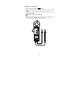
Page 12: ...to terminal and black one to the COM terminal Connect tip of the test leads to the points where the value of the resistance is needed Read the Ohm value from the LCD panel Note When measuring resista...

Page 13: ...ion selector to range Connect red test lead to terminal and black one to the COM terminal Connect tip of the test leads to the points where continuity is to be tested If the resistance is under 35 the...

Page 14: ...inals Switch the main function to Hz range Connect red test lead to terminal and black one to the COM terminal Connect tip of the test leads to the points where the frequency of the voltage signal is...

Page 15: ...pressing the clamp opening handle and insert the cable to be measured into the clamp Close the clamp and get the reading form the LCD panel Note When doing frequency measurement user should either us...

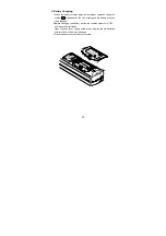
Page 16: ...pear on the LCD display and the battery will need to be changed 2 Before changing the battery switch the function selector to OFF and disconnect test leads Open the back cover using a screw driver Rep...

Page 17: ...tteries if the meter is not used for extended periods of time Do not store the meter in a high temperature humidity environment When measuring current keep the cable at the center of the clamp to get...

Page 18: ...GCBARM235 R0200 Armada Technologies Test Equipment Depot 800 517 8431 99 Washington Street Melrose MA 02176 TestEquipmentDepot com...

Reviews: