background image

Clamp Meter 


7


6.  MEASURING INSTRUCTION 

6-1  

ACA

ACmA Measurement: 

(1) Set the range selector switch to the desired position. The current 
to be measured should be within the selected measuring range. 

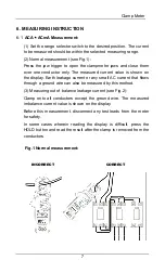
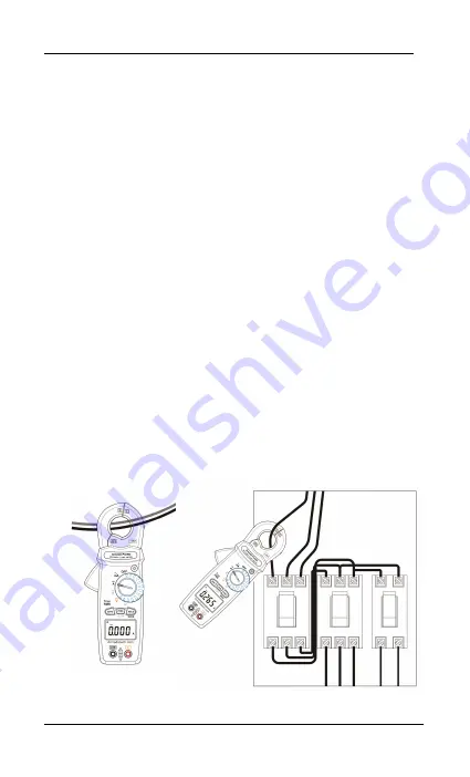
(2) Normal measurement (see Fig.1): 

Press the jaw trigger to open the clampmeter jaws and close them 
over one conductor only. The measured current value is shown on 
the display. Earth leakage current or any small AC current that flows 
through a ground wire can also be measured by this method. 

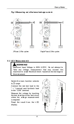
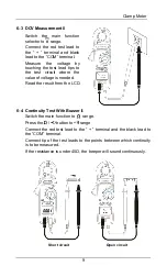
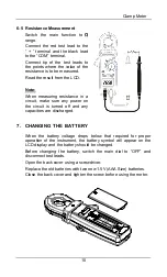
(3) Measuring out of balance leakage current (see Fig.2): 

Clamp onto all conductors except the ground wire. The measured 
imbalance current value is shown on the display. 

Before this measurement, disconnect any test leads from the meter 
for safety. 

In some cases wherein reading the display is difficult, press the 
HOLD button and read the result after the clamp is removed from the 
conductors. 


Fig.1 Normal measurement: 


INCORRECT   


      CORRECT


Summary of Contents for Pro95i

Page 1: ...Model Pro95i TRUE RMS MILLIAMP CLAMP METER...

Page 2: ......

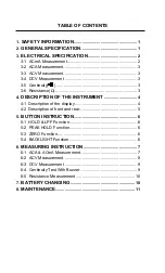
Page 3: ...4 DESCRIPTION OF THE INSTRUMENT 4 4 1 Description of the display 4 4 2 Description of front and rear 5 5 BUTTON INSTRUCTION 6 5 1 HOLD LPF Function 6 5 2 PEAK HOLD Function 6 5 3 ZERO Function 6 5 4 B...

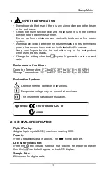
Page 4: ...ange the battery when the symbol appears to avoid incorrect data Environmental Conditions Operation Temperature 0 C to 40 C 32 F to 104 F 80 RH Storage Temperature 10 C to 60 C 14 F to 140 F 80 RH Exp...

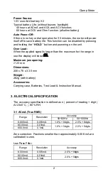
Page 5: ...han the maximum for the range in use the display will show Maximum jaw opening 23 mm Dimensions 206 x 76 x 33 5 mm Weight 262g with battery Accessories Carrying case Batteries Test Lead Instruction Ma...

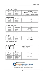
Page 6: ...0 001A 2 0 5dgts 60 00A 0 01A 3 3 ACV True RMS Range Resolution Accuracy 50 500Hz 60 00V 0 01V 1 0 3dgts 600 0V 0 1V Input impedance 2M 3 4 DCV Range Resolution Accuracy 60 00V 0 01V 1 0 2dgts 600 0V...

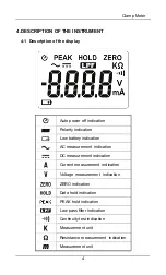
Page 7: ...on Low battery indication AC measurement indication DC measurement indication Current measurement indication Voltage measurement indication ZERO indication Data hold indication PEAK hold indication Lo...

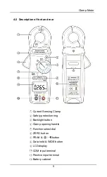
Page 8: ...1 Current Sensing Clamp 2 Safety protection ring 3 Backlight button 4 Clamp opening handle 5 Function select dial 6 ZERO button 7 PEAK button 8 Data hold WIDE button 9 LCD display 10 COM input termina...

Page 9: ...ion Press PEAK button to enter the PEAK mode the meter records the peak maximum value Press the PEAK button again to exit the peak mode When you turn the rotary switch to the Ohms Test position press...

Page 10: ...he display Earth leakage current or any small AC current that flows through a ground wire can also be measured by this method 3 Measuring out of balance leakage current see Fig 2 Clamp onto all conduc...

Page 11: ...e any voltage measurement that may exceed this maximum to avoid Electrical shock hazard and or damage to this instrument Switch the main function selector to range Connect the red test lead to the ter...

Page 12: ...uit where the value of voltage is needed Read the result from the LCD 6 4 Continuity Test With Buzzer Switch the main function to range Press the button to range Connect the red test lead to the termi...

Page 13: ...ke sure any power on the circuit is turned off and any capacitors are discharged 7 CHANGING THE BATTERY When the battery voltage drops below that required for proper operation of the instrument the ba...

Page 14: ...EMARK If the meter is not going to be used for a long time then please remove the battery and do not store the meter in a high temperature or high humidity environment Keep the cable in the center of...

Page 15: ......

Page 16: ...GCBARM265 I0200 Armada Technologies www armadatech com...

Reviews: