background image

SpecterOS4x Operation Manual 

Page 4 


1.3 

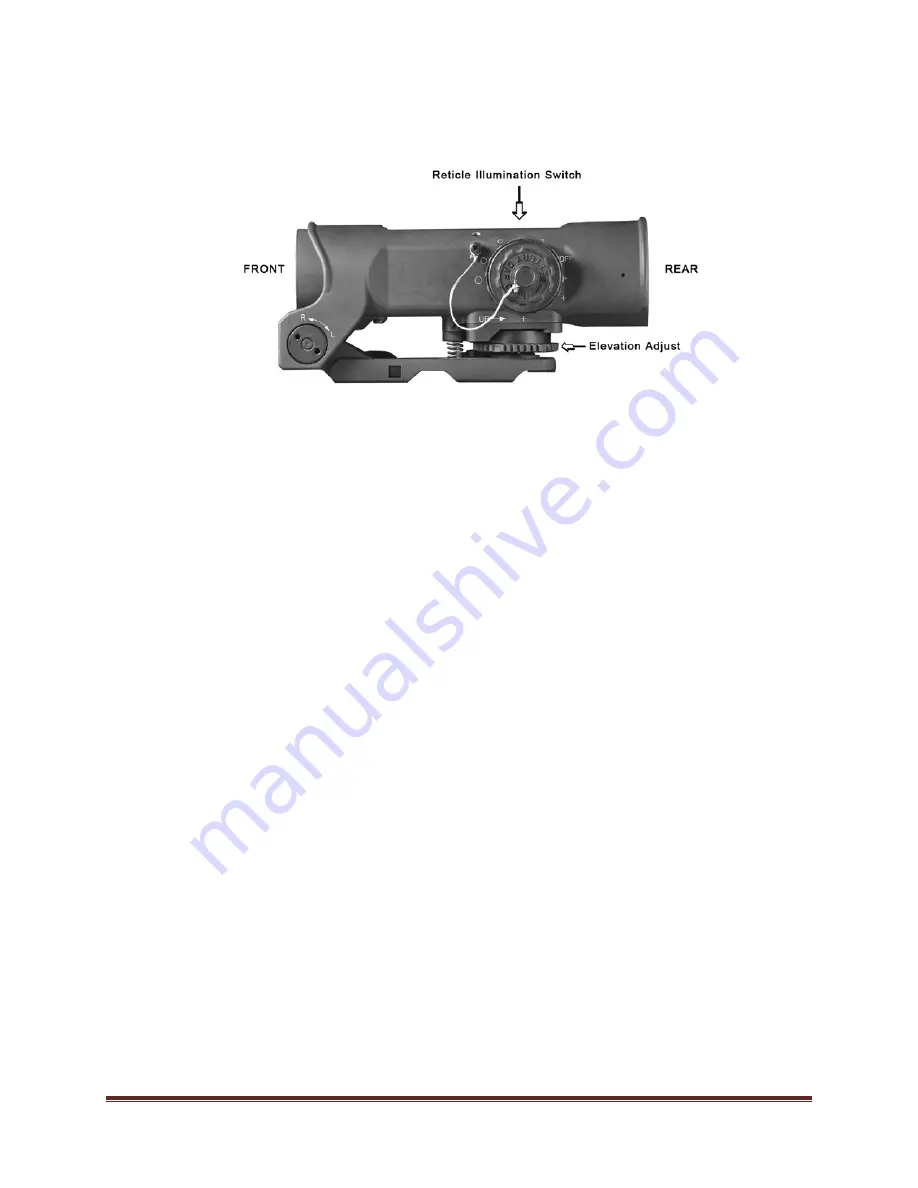
SpecterOS4x Controls and Terminology 


Figure 1-3    Left Side View and Selected Controls 


1.3.1 

Auxiliary Sight Mounting Capability


The SpecterOS4x does not incorporate Integral back-up iron sights. Should the user desire, an auxiliary 
sight (mini Red Dot Sight) may be installed on top of the SpecterOS4x in conjunction with the optional 
MRD Mounting Kit. 


1.3.2 Battery 

Cap


The fluted battery cap sits on top of the Illumination Rotary Switch.  It can be removed by hand by 
unscrewing it counter clockwise (CCW).  The battery cap should only be tightened by hand until snug so 
that it can later be removed by hand.   
  

1.3.3 

Mount Locking Levers


The locking levers are used to secure the sight to the weapon’s “Picatinny” rail.  SpecterOS4x uses 2 
ARMS type low profile locking levers that point rearward when locked.  The mount base also provides for 
additional tie/wire wrap points so that the ARMS levers can be locked in place if desired. 
  

1.3.4 

Elevation Zeroing Dial


The zero dial is located at the lower rear of the mount.  This dial allows for elevation zeroing only while 
the elevation zeroing lock is disengaged. 
  

1.3.5 

Elevation Zeroing Lock


The elevation zeroing lock (silver tab) is located just above the elevation zeroing dial.  It is only used 
during elevation zeroing.   Move the lock UP to permit ½ MOA per click elevation zeroing.  Move the lock 
DOWN to lock the elevation zero.  

 
Important: 

To prevent damage

 be sure 

that the lock is

 fully disengaged 

before attempting to turn the 

elevation zeroing dial.


Summary of Contents for SpecterOS4x Optical Sight

Page 1: ...SpecterOS4x Optical Sight Operation Manual ARMAMENT TECHNOLOGY INCORPORATED 3045 ROBIE STREET SUITE 113 HALIFAX NS B3K 4P6 CANADA sales armament com www armament com...

Page 2: ...2 QUICK START Page 6 2 1 Mounting Page 6 2 2 SpecterOS4x Operation Page 6 2 3 Quick Zeroing Page 7 2 4 Reticle Illumination Page 8 2 5 Changing the Battery Page 9 CHAPTER 3 OPERATION Page 10 3 1 Gener...

Page 3: ...r low light conditions The ballistically compensated reticle consists of a cross hair or chevron with horizontal stadia lines for shooting at various ranges The SFOV4 C1 model incorporates a Vertical...

Page 4: ...ter 32 mm Reticle Pattern Ballistic compensated crosshair Exit Pupil 8 0 mm Illumination LED Eye Relief 70mm Operating Temp 40 to 65 C Optical Axis Height 39mm Storage Temp 40 to 85 C Zeroing Range 60...

Page 5: ...Levers The locking levers are used to secure the sight to the weapon s Picatinny rail SpecterOS4x uses 2 ARMS type low profile locking levers that point rearward when locked The mount base also provi...

Page 6: ...point of impact to the right Each click moves the point of impact Minute of Angle MOA approximately at 100 yards 1 3 8 Reticle Illumination Knob Rotation of the knob illuminates the reticle at varyin...

Page 7: ...RELIEF When viewing through the sight proper eye relief causes the scene field of view to be a circular and sharp image see Figure 2 2 It may be necessary to move the optical sight either backwards or...

Page 8: ...OA approximately 1 2 at 100 yards Figure 2 4 Elevation zeroing uses the elevation dial the bottom rear of the mount Unlock the zeroing lock silver tab by raising it up as far as it will go Be sure tha...

Page 9: ...he centre of the crosshairs cross or chevron A Range Estimating and Drop Compensation Reticle Each reticle mode has multiple brightness settings and are set by the Illumination switch rotary on the le...

Page 10: ...umination switch to desired reticle brightness setting 2 5 CHANGING THE BATTERY To change the battery remove the battery cover by gripping the smaller diameter fluted section of the Illumination Switc...

Page 11: ...y For extra mounting security the mount provides slots to accommodate plastic or wire tie wraps so that the levers can be locked into their closed position The sight is now mounted on the weapon 3 3 M...

Page 12: ...back down fully 3 5 Zeroing Zeroing should be performed at 100 meters It is recommended that the marksman fires three round groups and make adjustments based upon the estimated geometric centre of th...

Page 13: ...w rotate With the lock disengaged rotate the elevation zeroing dial to the left to move the MPI down or to the right to move the MPI up RANGE IN METRES MPI MOVEMENT IN mm PER CLICK OF ADJUSTMENT MPI M...

Page 14: ...line also coincides with the 100 meter aiming point This reticle pattern is designed to be zeroed at 100 meters 3 6 2 A central aiming feature either a fine cross or a chevron is placed at the reticl...

Page 15: ...Vertical Subtention Optical Rangefinder VSOR allows the marksman to estimate the distance to targets by matching the height of a known object within the field of view The vertical distance for range...

Page 16: ...terDR sight in solvents DO NOT use hot water to clean the sight If mud or hardened dirt are on or near the lens Flush with cold or warm water and gently wipe with a moistened tissue Repeat the procedu...

Reviews: