59
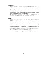
Equipment Set Up
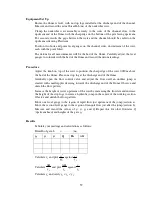
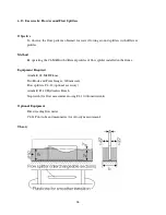
Ensure the flume is level, with no stop logs installed at the discharge end of the channel.
Measure and record the actual breadth b (m) of the undershot weir.
Clamp the undershot weir assembly securely to the sides of the channel close to the
upstream end of the flume with the sharp edge on the bottom of the gate facing upstream.
For accurate results the gaps between the weir and the channel should be sealed on the
upstream side using Plasticine.
Position two hook and point level gauges on the channel sides, downstream of the weir,
each with the point fitted.
The datum for all measurements will be the bed of the flume. Carefully adjust the level
gauges to coincide with the bed of the flume and record the datum readings.
Procedure
Adjust the knob on top of the weir to position the sharp edge of the weir 0.020m above
the bed of the flume. Place one stop log at the discharge end of the flume.
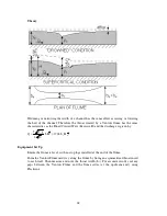
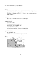
Gradually open the flow control valve and adjust the flow until an undular jump is
created with small ripples decaying towards the discharge end of the flume. Observe and
sketch the flow pattern.
Increase the height of water upstream of the weir by increasing the flowrate and increase
the height of the stop logs to create a hydraulic jump in the centre of the working section.
Observe and sketch the flow pattern.
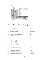
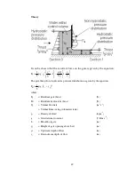
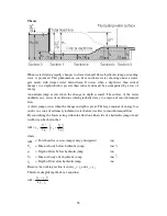
Move one level gauge to the region of rapid flow just upstream of the jump (section a).
Move the second level gauge to the region of tranquil flow just after the jump (section b).
Measure and record the values of y
1
, y
3
, y
g
and Q. Repeat this for other flowrates Q
(upstream head) and heights of the gate y
g
.
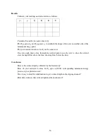
Results
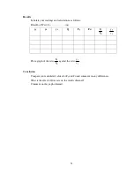
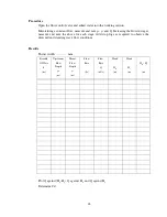
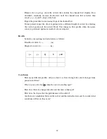
Tabulate your readings and calculations as follows:
Breadth of gate, b
=…………(m)
y
g
y
1
y
3
Q
H
b
H
∆
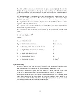
Calculate v
1
and plot
1
2
1
gy
v
against
1
3
y
y
Calculate
1
y
H
∆
and plot
1
y
H
∆
against
1
3
y
y
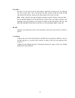
Calculate y
c
and verify y
1
< y
c
< y
3
.

