75
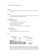
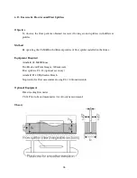
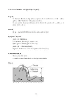
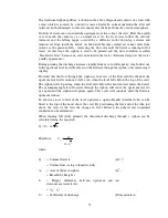
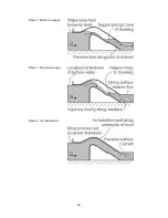
The traditional siphon spillway is shown in the above diagram and consists of a weir with
a crest which is covered by a hood to create a barrel. In normal operation the inlet and
outlet are both submerged so that air cannot enter the barrel from the outside atmosphere.
No flow of water can occur until the upstream level rises above the crest. Flow then spills
over in much the same way as a normal weir. As the level rises further the velocity
increases and the falling nappe, assisted by a deflector in the down-leg, entrains and
removes air from inside the barrel. As the barrel becomes sealed, air cannot enter from
outside so the pressure falls - increasing the flow rate until the barrel is running full of
water. At this stage the siphon is said to be primed and the flow condition is called
“blackwater flow” because no air is entrained in the water. (Entrained air gives the water
a milky appearance.)
During priming the discharge increases rapidly from zero to full capacity. Any further rise
in the upstream level has little effect on the flowrate through the siphon, only increasing it
slightly.
Provided that the flow through the siphon is in excess of the flow into the channel, the
upstream level will continue to fall, even when the level falls below the top of the crest.
The siphon will stop acting when the level falls below the hood and air enters the barrel.
The accompanying fall in flowrate through the siphon will cause the upstream level to
rise again and the siphon will prime again. This cycle will continue until the flowrate
upstream reduces.
To achieve closer control of the level upstream a siphon breaker (breather tube) can be
fitted to the top of the hood above the crest. By positioning the free end of the tube just
above the crest of the weir the change in level between the primed and de-primed
condition can be minimised.
When running full (fully primed) the theoretical discharge through a siphon can be
calculated using the equation:
h
A
C
Q
t
d
=
Therefore:
2
1
h
A
Q
C
t
d
⋅
=
where:
Q
= Volume flowrate
(m
3
s
-1
)
= Volume/time (using volumetric tank)
A
t
= Area of throat in siphon
(m
2
)
= Breadth b x Height z
h
= Height difference between upstream and
downstream water levels
(m)
= (y
0
– y
1
)
C
d
= Coefficient of discharge
(Dimensionless)


