background image

Issue 1324

507120-01

Page 8 of 18

The air handler is provided with 3/4” NPT condensate drain 

connections.

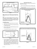
Sloping the Drain

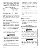
Make sure the unit is sloped (similar to the slope shown 

in Figure 10) so that the drain pan will empty completely 

without water standing in the pan.

Figure 10

Sloping the Drain

INSTALL CONDENSATE DRAIN 

1.  Remove the appropriate drain knockouts.  If necessary, 

remove the indoor coil assembly from the cabinet. 

2.  Connect primary drain line connection to the primary 

drain pan connection.  The primary drain connection is 

flush with the bottom of the inside of the pan.  Secondary 

connection is raised above the bottom of the inside of 

the pan. 

NOTE:


When making drain fitting connections to the drain 

pan,  hand  tighten  the  fitting  and  use  a  sealant.    Over-

tightening the fittings can split connections on the drain pan. 

3.  If the auxiliary drain line is to be used, remove the plug 

and route the drain line so that water draining from the 

outlet will be easily noticed by the homeowner. The 

auxiliary drain line does not required venting or a trap.  

Refer to local codes. 

4.  After removal of drain pan plugs, check the drain port 

to see if holes have been drilled.  If not drilled, use a 

19/32” bit to drill out the primary drain hole; use a 3/8” 

drill bit for the secondary drain hole.  Remove all drill 

shavings. 

5.  Make sure drain ports and drain pan are free of all 

debris. 

6.  Plug and check any unused drain pan openings for 

tightness.  Torque plugs to 30 in. lb. to prevent water 

leaks or seepage from the drain pan. 

7.  Install a 2” trap in the primary drain lines as close to the 

unit as practical (see figure 9). Make sure the top of the 

trap is below the connection to the drain pan to allow 

complete drainage of the pan. 

NOTE:


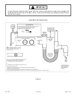
Horizontal runs must have an anti-siphon air vent 

(standpipe) installed ahead of the horizontal run 

(See 

F

igure 

9). 

 An extremely long horizontal run may require an 

oversized drain line to eliminate air trapping. 

NOTE:


Do not operate air handler without a drain trap.  

The condensate drain is on the negative pressure side of 

the  blower;  therefore,  air  being  pulled  through  the 

condensate line will prevent positive drainage without a 

proper trap. 

8.  Route the drain line to the outside or to an appropriate 

drain.  Drain lines must be installed so they do not block 

service access to the front of the air handler.  A 24” 

clearance is required for filter, coil, or blower removal 

and service access. 

NOTE:


Check local codes before connecting the drain line 

to an existing drainage system.  

Insulate the drain lines 

where sweating could cause water damage.


TEST CONDENSATE DRAIN 

Test the drain pan and drain line after installation: 

1.  Pour several quarts of water into drain pan, enough to 

fill drain trap and line. 

2.  Check to make sure the drain pan is draining completely, 

no leaks are found in drain line fittings, and water is 

draining from the end of the primary drain line. 

3.  Correct any leaks found. 

Duct System and Filters 

DUCT SYSTEM


The air handler is provided with flanges for the connection 

of the plenum and ducts. The air handler is equipped with 

flanges that can form a filter rack for the installation of the 

air filter, or the filter may be installed as part of the return 

air duct system. 

A  field-fabricated  secondary  drain  pan,  with  a  drain 

pipe to the outside of the building, is required in all 

installations over a finished living space or in any area 

that may be damaged by overflow from the main drain 

pan.  In some localities, local codes may require a 

secondary drain pan for any horizontal installation.


IMPORTANT

Summary of Contents for BCE3M 18

Page 1: ...Condensate Drain 7 Duct Systems and Filters 8 Connecting Refrigerant Lines 9 Sealing the Unit 9 Electrical Connections 10 Airflow Cooling Blower Speed 12 Check Out Procedures 13 Operation13 Maintenan...

Page 2: ...9 12 1 4 311 18 7 8 479 5 3 4 146 16 7 8 429 17 3 4 451 17 432 19 7 8 505 20 3 4 527 19 3 8 492 5 1 2 140 43 1092 18 1 2 470 22 559 6 152 16 406 5 1 2 140 13 1 2 343 17 3 4 451 17 432 16 1 2 419 20 3...

Page 3: ...space routing requirements for refrigerant line condensate disposal filters duct system wiring and accessibility for service Refer to the air handler rating plate on the air handler for specific infor...

Page 4: ...s are provided for electrical wiring entrance For ease in installation it is best to make any necessary coil configuration changes before setting air handler in place For all performance testing units...

Page 5: ...ntal configuration is shown in Figure 3 5 If the unit is suspended the entire length of the cabinet must be supported If you use a chain or strap use a piece of angle iron or sheet metal attached to t...

Page 6: ...ugged Remove the plugs from the front drain pan ports 5 Re install modified coil drain pan assembly in air handler in the same orientation as before Figures 6 and 7 Figure 6 Install Main Drain Pan Mou...

Page 7: ...ure 9 On units of this type where the blower draws rather than blows air through the coil traps must be installed in the condensate drain lines primary and auxiliary if used Traps prevent the blower f...

Page 8: ...he drain pan to allow complete drainage of the pan NOTE Horizontal runs must have an anti siphon air vent standpipe installed ahead of the horizontal run See Figure 9 An extremely long horizontal run...

Page 9: ...oid damaging the rubber grommets in the cabinet while brazing slide the rubber grommets over the refrigerant lines until they are away from the heat source 5 Braze using an alloy of silver or copper a...

Page 10: ...t all power supplies 2 Remove the air handler access panel 3 Route the field supply wires to the air handler electrical connection box 4 Use UL listed wire nuts to connect the field supply conductors...

Page 11: ...Page 11 of 18 Issue 1324 507120 01 Figure 12 Low Voltage Connections 3 Speed PSC Motor...

Page 12: ...rom the 4 pin blower motor connector NOTE Reuse the factory installed plastic cap on whichever wire is not used 6 Replace all panels 7 Reconnect power CHANGE BLOWER SPEED NOTE Refer to wiring diagram...

Page 13: ...elay coil and then the indoor blower relay energizes The normally open contacts close causing the indoor blower motor to operate The circuit between R and Y is completed closing the circuit to the con...

Page 14: ...emperature of the cabinet The temperature humidity difference between the inside and outside of the cabinet can cause condensation on the inside or outside of the cabinet which leads to sheet metal co...

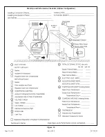
Page 15: ...Page 15 of 18 Issue 1324 507120 01 Start Up and Performance Checklist Horizontal Configuration Figure 14...

Page 16: ...Issue 1324 507120 01 Page 16 of 18 Figure 15 Start Up and Performance Checklist Upflow Configuration...

Page 17: ...rnish the following information a complete model and serial number b proof of required periodic maintenance installation date and location and c an accurate description of the problem WARRANTY LIMITAT...

Page 18: ...odification change or alteration of the unit except as expressly directed in writing by Allied Air 4 Improper use accident neglect or unreasonable use or operation of the unit including operation of e...

Reviews: