background image

507789-01

Issue 2007

Page 14 of 24

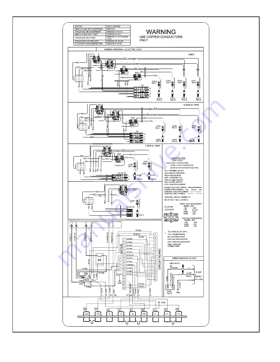
4KW & 5KW

Figure 14. Typical Wiring Diagram – BCE5V 

Air Handler with Electric Heat – (Variable-Speed Motor)

Summary of Contents for BCE5V Series

Page 1: ...erant Lines 9 Sealing the Unit 11 Electrical Connections 12 BDC3 Blower Control 16 Adjusting the Blower Speed 16 Blower Performance 17 Checkout Procedures 21 Professional Maintenance 22 Homeowner Main...

Page 2: ...19 2 3 4 70 3 1 2 89 PIPING PLATE 4 3 4 121 4 3 8 111 2 3 8 60 CONDENSATE DRAINS 2 Upflow and Downflow SUCTION LINE CONDENSATE DRAIN PIPING PLATE 3 2 1 4 x 3 3 4 NOTE Unit is shipped configured for ho...

Page 3: ...plied in separate equipment before starting the installation In addition to conforming to manufacturer s installation instructions and local municipal building codes installation of air handler units...

Page 4: ...aced upon construction completion Installation Clearances Non Ducted Return Closet Installation The air handler can be installed in a closet with a false bottom to form a return air plenum It may also...

Page 5: ...hand applications The coil may tip into the drain pan once it is clear of the cabinet Support the coil when removing it IMPORTANT NOTE When the unit is installed in horizontal applications a secondary...

Page 6: ...s the horizontal drain pan as illustrated in Detail A in Figure 5 NOTE Be very careful when reinstalling the screws into the coil end plate engaging holes Misaligned screws may damage the coil 9 From...

Page 7: ...ARY DRAIN PLUG UNSCREW PLUGS AND CONNECT PROPERLY SIZED FIELD PROVIDED FITTINGS AND DRAIN LINES GREEN MAIN DRAIN PLUG Figure 7 Drain Line Connections 2 Install properly sized field provided connection...

Page 8: ...2 CUT TO REQUIRED LENGTH SIDE VIEW Figure 8 Typical Main and Overflow Drain 4 Check again to ensure drain ports and drain pan are free of all debris 5 Plug and check any unused drain pan openings for...

Page 9: ...provided by the filter manufacturer against the data given in the appropriate Product Specifications Additional information is provided in Service and Application Note ACC002 August 2000 IMPORTANT Ins...

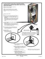
Page 10: ...RE INSTALLING EITHER REMOVE OR PUSH PIPE WRAPPING BACK THROUGH HOLE IN PIPING PLATE BEFORE LINE SET CONNECTION AND BRAZING CONNECT PIPES NOTE REFRIGERANT LINE SETS SHOULD BE ROUTED TO ALLOW FILTER ACC...

Page 11: ...ng brazing alloys and flux CAUTION Recommended line length is 50 or less If more than 50 line set is required contact Technical Services NOTE Sealing the Unit Seal the unit so that warm air is not all...

Page 12: ...ave multiple power supplies WARNING Wiring must conform to the current National Electric Code ANSI NFPA No 70 or Canadian Electric Code Part I CSA Standard C22 1 and local building codes Refer to foll...

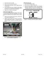
Page 13: ...Figure 12 1 Remove the two screws that secure the control panel to the cabinet Slide panel out 2 Slide the control panel into the notch on the electric heat mounting panel Figure 11 Using the screws r...

Page 14: ...507789 01 Issue 2007 Page 14 of 24 4KW 5KW Figure 14 Typical Wiring Diagram BCE5V Air Handler with Electric Heat Variable Speed Motor...

Page 15: ...507789 01 Issue 2007 Page 15 of 24 WARNING USE COPPER CONDUCTORS ONLY Y2 Figure 15 Low Voltage Connections Variable Speed Motor...

Page 16: ...CFM LED will flash 10 times If the CFM is 1150 CFM LED will flash 11 full times plus one fast or half flash At times the light may appear to flicker or glow This is normal and occurs when the control...

Page 17: ...tage outdoor unit the air volume is 70 of the COOL jumper selection This arrangement providesforadditionaldehumidification during standard first stage cooling See the blower performance tables for var...

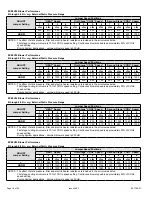
Page 18: ...d is approximately 50 of COOL speed setting Zoning System applications minimum blower speed is 250 cfm BCE5V36 Blower Performance 0 through 0 80 in w g External Static Pressure Range ADJUST Jumper Set...

Page 19: ...setting Continuous blower speed is approximately 50 of COOL speed setting Zoning System applications minimum blower speed is 450 cfm Operating Sequence System Demand System Response System Condition S...

Page 20: ...int by allowing the room space to maintain a cooler room thermostat setpoint Room Thermostat Calls for First and Second Stage Cooling BASIC MODE only active on a Y1 thermostat demand Normal Operation...

Page 21: ...DEMAND 7 1 2 MIN 82 CFM 100 CFM 1 2 MIN 50 CFM Checkout Procedures NOTE Refer to outdoor unit installation instructions for system start up instructions and refrigerant charging instructions Pre Start...

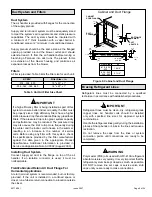
Page 22: ...eplace a cleanable high velocity filter with a disposable low velocity filter unless return air system is properly sized for it If water should start coming from the secondary drain line a problem exi...

Page 23: ...ng Mode Return Duct Temperature ___________ THERMOSTAT Adjusted and Programmed Return External Static ______ ______ Total External Static ______ ______ 6 Supply Duct Temperature ___________ Temperatur...

Page 24: ..._____ Total External Static ______ ______ 6 6 Supply Duct Temperature ___________ Temperature Drop ___________ TEMPERATURE RISE Heating Mode Return Duct Temperature __________ Supply Duct Temperature...

Reviews: