507640-05
Page 19 of 25
Issue 2245
Defrost System
Demand Defrost System
The demand defrost system measures differential
temperatures to detect when the system is performing
poorly because of ice build-up on the outdoor coil. The
system “self-calibrates” when the defrost system starts
and after each system defrost cycle. The demand defrost
components on the control board are listed below.
NOTE:
The demand defrost system accurately measures
the performance of the system as frost accumulates on the
outdoor coil. This typically will translate into longer running
time between defrost cycles as more frost accumulates on
the outdoor coil before the board initiates defrost cycles.
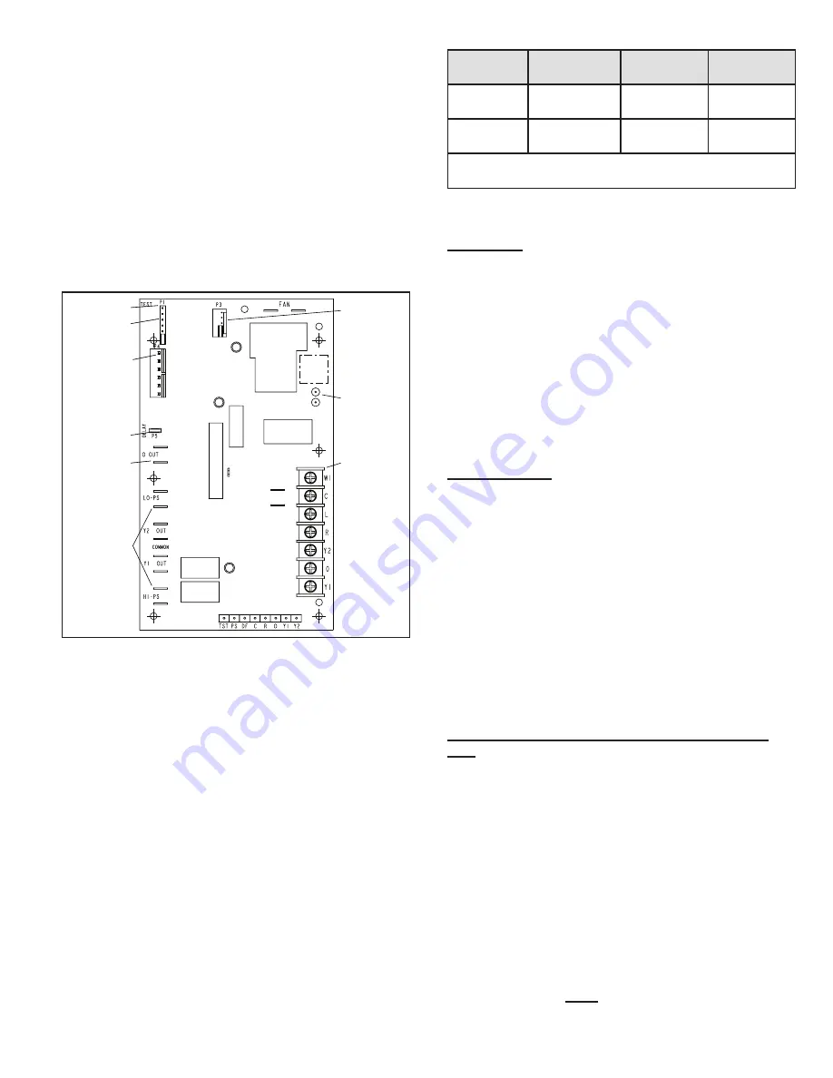
Figure 9. Defrost Control Board
(2-Ton Units)
TEST PINS
DEFROST
TERMINATION
PIN SETTINGS
SENSOR
PLUG-IN
(COIL &
AMBIENT
SENSORS)
DELAY PINS
REVERSING
VALVE
PRESSURE
SWITCH
CIRCUIT
CONNECTIONS
LOW
AMBIENT
THERMOSTAT
PINS
DIAGNOSTIC
LEDs
24V TERMINAL
STRIP
CONNECTIONS
Note -
Component
Locations Vary
by Board
Manufacturer
Defrost System Sensors
Sensors connect to the defrost board through a field–
replaceable harness assembly that plugs into the board.
Through the sensors, the board detects outdoor ambient
and coil fault conditions. As the detected temperature
changes, the resistance across the sensor changes.
Sensor resistance values can be checked by ohming
across pins.
NOTE:
When checking the ohms across a sensor, be
aware that a sensor showing a resistance value that is not
within the range shown, may be performing as designed.
However, if a shorted or open circuit is detected, then the
sensor may be faulty and the sensor harness will needs to
be replaced.
Sensor
Temperature
Range
°
F (
°
C)
Red LED
(DS1)
Pins / Wire
Color
Outdoor
(ambient)
-35 (-37) to
120 (48)
280,000 to
3750
3 & 4
(black)
Coil
-35 (-37) to
120 (48)
280,000 to
3750
5 & 6
(brown)
NOTE
: Sensor resistance decreases as sensed temperature
increases.
Table 3. Sensor Temp. / Resistance Range
Coil Sensor
The coil temperature sensor considers outdoor
temperatures below -35°F (-37°C) or above 120°F (48°C)
as a fault. If the coil temperature sensor is detected as
being open, shorted or out of the temperature range
of the sensor, the board will not perform demand or
time/temperature defrost operation and will display the
appropriate fault code. Heating and cooling operation will
be allowed in this fault condition.
NOTE:
The coil temperature probe is designed with a
spring clip to allow mounting to the outside coil tubing. Coil
sensor location is important for proper defrost operation.
Ambient Sensor
The ambient sensor considers outdoor temperatures
below -35°F (-37°C) or above 120°F (48°C) as a fault. If the
ambient sensor is detected as being open, shorted or out
of the temperature range of the sensor, the board will not
perform demand defrost operation. The board will revert
to time/temperature defrost operation and will display the
appropriate fault code. Heating and cooling operation will
be allowed in this fault condition.
NOTE:
Within a single room thermostat demand, if 5-strikes
occur, the board will lockout the unit. Control board 24 volt
power “R” must be cycled “OFF” or the “TEST” pins on
board must be shorted between 1 to 2 seconds to reset
the board.
Defrost Temperature Termination Shunt (Jumper)
Pins
The defrost board selections are: 50, 70, 90, and 100°F
(10, 21, 32 and 38°C). The shunt termination pin is factory
set at 50°F (10°C). If the temperature shunt is not installed,
the default termination temperature is 90°F (32°C).
Delay Mode
The defrost system has a field-selectable function to
reduce occasional sounds that may occur while the unit is
cycling in and out of the defrost mode. When a jumper is
installed on the DELAY pins, the compressor will be cycled
off for 30 seconds going in and out of the defrost mode.
Units are shipped with jumper installed on DELAY pins.
NOTE:
The 30 second compressor delay feature (known
as the quiet shift)
must
be deactivated during any unit


