10
Pneumatic Piping for Air Operated Humidifier–AM Models
STEP 9A: Install Pneumatic Piping
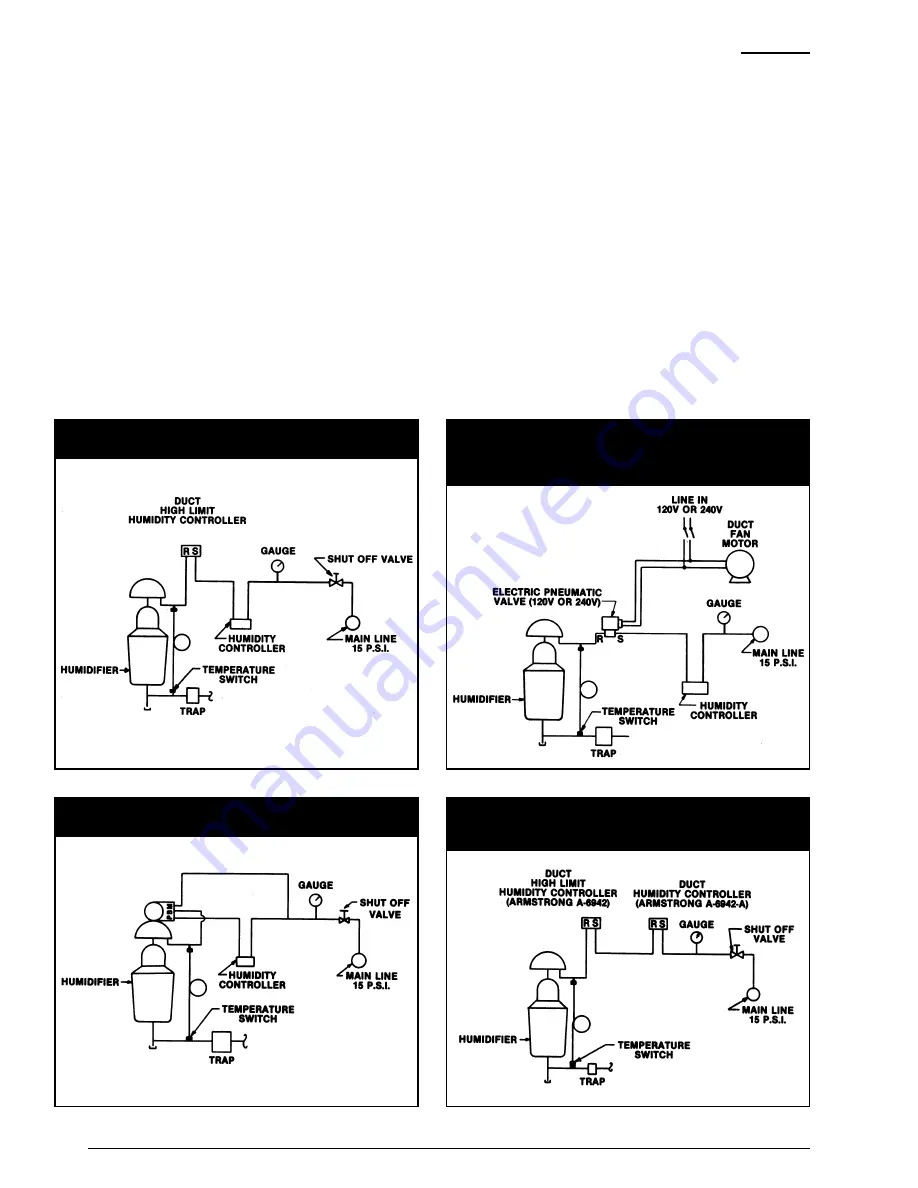
in accordance with Fig. 10-1 or
engineer’s layout.
a. Control Air Supply. Unless
otherwise specified, air supply for
Armstrong Humidifiers should be 20
psig maximum. This air must be
clean and dry.
b. Air Piping.
1
¼
4
" plastic tubing or
equivalent is recommended for all
air connections.
Note:
When a pilot positioner is
furnished, it should be hooked up as
shown in Fig. 10-3.
STEP 10A: Install and Connect
Humidity Controller
as specified by
engineer in accordance with
manufacturer’s instructions. If location
is not specified it may be installed in
the area controlled or in either the
return air or exhaust air ducts.
Auxiliary Controls
Hi-Limit Duct Humidity Controller.
A
high limit humidistat is recommended
in the duct at least 10 feet
downstream from the humidifier to
override the controlling humidistat.
This high-limit humidistat automatically
prevents local saturation at the point of
steam introduction. It also prevents
overloading the duct with vapor in the
event of failure of air conditioning
system components, incorrect control
settings or tampering. See Fig. 10-1.
Interlocks for Shutdowns.
Humidifiers should be interlocked with
fans for shutdown on power failure or
other system trouble. Interlock should
be such that the valve will go to the
closed position on a system shutdown
rather than be locked in its position at
time of shutdown. See Figure 10-2.
Temperature Switch for Automatic
Warm Up.
For systems that may be
started and stopped, such as in
laboratories or in operations which
shut down each weekend, a
temperature switch is recommended
on the condensate outlet from the
humidifier. Your Armstrong
Representative can supply an
immersion type unit that will
automatically keep valves closed
during warm up period after shutdown.
This will avoid the discharge of
condensate that can occur if steam is
admitted to cold humidifier piping
when the humidifier valve is open See
Fig. 10-1.
Figure 10-1. Standard compressed air hook-up for all pneumatically
operated humidifiers. Pneumatic temperature switch shown.
Figure 10-3. Compressed air hook-up for humidifiers utilizing a
Honeywell MP953-F pneumatic operator with pilot positioner.
Figure 10-4. Compressed air hook-up for humidifiers utilizing two
Armstrong Duct Humidity Controllers, one as the humidity controller,
the other as a high limit controller.
Figure 10-2. Compressed air hook-up for air operated humidifiers
incorporating safety interlock for shutdown in the event of power failure
to fan and an electric temperature switch to prevent water discharge on
start-up when humidifier piping is cold.


