background image

Bulletin 549-A

This bulletin should be used by experienced personnel as a guide to the installation and maintenance of AM-91A, 
-92A, 93A; AMAF-91A, -92A, -93A; AMEF-91A, -92A, -93A; FSA-91A, -92A, -93A; VSA-91A, -92A, -93A direct area humidifi ers.  Se-
lection or installation of equipment should always be accompanied by competent technical assistance.  We encourage you to contact 
Armstrong or its local representative if further information is required.

Installation and Operation

AM-91A, -92A, 93A; AMAF-91A, -92A, -93A; AMEF-91A, -92A, -93A; 

FSA-91A, -92A, -93A; VSA-91A, -92A, -93A

Humidifi ers for Direct Area Humidifi cation

Step 1.  Check Shipment Against Packing List

All components are listed on the packing 
slip.  Report any shortages immediately.  If 
the humidi

fi

 er or accessories have been 

damaged in transit, notify us and 

fi

 le claim 

with the transportation company.

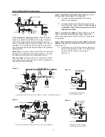
Step 2.  Mount the Humidifi er

Support it from the ceiling, Fig. 1-3, or bracket 
it to a column as shown in Fig. 1-4.  There are 
holes on both sides of the humidi

fi

 er for mounting 

purposes.

Exception:

 Where supply and return connections 

for the 91 & 92 size are short, a pipe hanger to 
the steam supply line should be suf

fi

 cient.

Figure 1-3.

Figure 1-4.

Humidifi er suspended from ceiling.

Humidifi er bracketed to column.

*Standard spring — furnished when no spring range is specifi ed.

AM, VSA Models

AMEF, AMAF, 
FSA Models

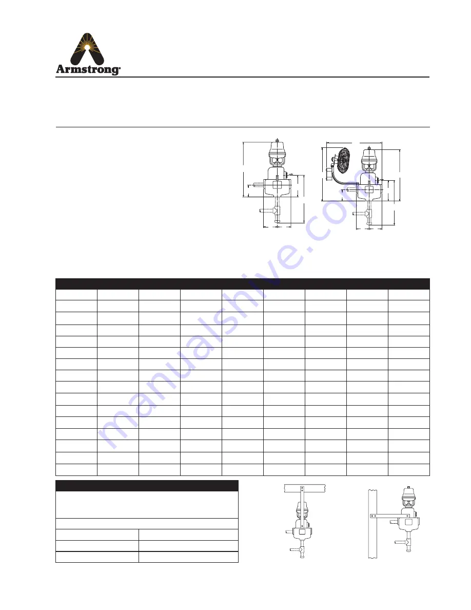
Figure 1-1.

Figure 1-2.

Dimensions, Armstrong Area Humidifi ers.  Fig. 1-1 VSA, AM models do not 
have fans.  Fig. 1-2 FSA, AMEF models have electrically operated fans.  AMAF 
models utilize air powered fans.

Installation Procedure

B

C

D

F

J

E

H

G

C

D

F

B

J

E

  Table 1-1

Model No.

B

C

D

E

F

G

H

J

AM-91A

15-15/16”

3-3/8”

3-13/16”

6-1/16”

3-1/16”

13-1/4”

AMAF-91A

15-15/16”

3-3/8”

3-13/16”

6-1/16”

3-1/16”

15-5/8”

14-9/16”

13-1/4”

AMEF-91A

15-15/16”

3-3/8”

3-13/16”

6-1/16”

3-1/16”

18-9/16”

15-3/4”

13-1/4”

FSA-91A

10-7/8”

3-3/8”

3-13/16”

6-1/16”

3-1/16”

17-3/8”

15-3/4”

13-1/4”

VSA-91A

10-7/8”

3-3/8”

3-13/16”

6-1/16”

3-1/16”

13-1/4”

AM-92A

15-15/16”

3-3/8”

3-13/16”

6-1/16”

3-13/16”

13-1/4”

AMAF-92A

15-15/16”

3-3/8”

3-13/16”

6-1/16”

3-13/16”

15-5/8”

14-9/16”

13-1/4”

AMEF-92A

15-15/16”

3-3/8”

3-13/16”

6-1/16”

3-13/16”

18-9/16”

15-3/4”

13-1/4”

FSA-92A

10-7/8”

3-3/8”

3-13/16”

6-1/16”

3-13/16”

17-3/8”

15-3/4”

13-1/4”

VSA-92A

10-7/8”

3-3/8”

3-13/16”

6-1/16”

3-13/16”

13-1/4”

AM-93A

25-1/2”

4-5/8”

4-3/4”

9”

4-3/4”

24”

AMAF-93A

25-1/2”

4-5/8”

4-3/4”

9”

4-3/4”

17-3/4”

24”

AMEF-93A

25-1/2”

4-5/8”

4-3/4”

9”

4-3/4”

21”

18-1/4”

24”

FSA-93A

20-3/8”

4-5/8”

4-3/4”

9”

4-3/4”

21”

18-1/4”

24”

VSA-93A

20-3/8”

4-5/8”

4-3/4”

9”

4-3/4”

24”

  Table 1-2

Note: AM models 91, 92 and 93 shown on this bulletin are furnished with 

Armstrong C-1801 pneumatic operators. Operator Spring Ranges for 

pneumatically controlled humidifi ers.

Armstrong C-1801

Operating Range

Adjustable Start Points

5 lbs.

3 psig min. - 6 psig max.

*10 lbs.

3 psig min. - 6 psig max.

Summary of Contents for AM-91A

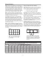
Page 1: ...spring range is specified AM VSA Models AMEF AMAF FSA Models Figure 1 1 Figure 1 2 Dimensions Armstrong Area Humidifiers Fig 1 1 VSA AM models do not have fans Fig 1 2 FSA AMEF models have electrically operated fans AMAF models utilize air powered fans Installation Procedure B C D F J E H G C D F B J E Table 1 1 Model No B C D E F G H J AM 91A 15 15 16 3 3 8 3 13 16 6 1 16 3 1 16 13 1 4 AMAF 91A 1...

Page 2: ...1 1 4 1 1 4 1 1 4 3 4 Steam Pipe Capacities For computing ability of piping to deliver an adequate supply of steam to humidifier Capacities shown are in pounds per hour Table 2 2 Steam Pipe Capacity at 5 psi Pipe Size in Pressure drop psi per 100 ft of pipe length 1 8 1 4 1 2 3 4 1 1 24 31 44 54 62 1 1 4 52 68 97 120 140 1 1 2 81 100 150 180 210 2 160 210 300 370 430 2 1 2 270 350 500 610 710 Tabl...

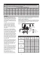
Page 3: ...ve Relief Valve A pressure relief valve between the humidifier and pressure reducing valve is a good insurance Humidi fier bodies are only rated for 60 psig steam service Pressure Gage A pressure gage or connection for install ing a gage between reducing valve and the humidifier may save its cost many times over Air and Electrical Connections 10 Min Strainer Steam Trap Steam Trap Steam Supply Dirt...

Page 4: ...r size and type of units required and the location of both humidifier and humidity controllers Sizing and location with natural ventilation These are the average industrial humidification applications with Room temperatures 65 to 80 Relative humidities 35 to 80 Natural ventilation i e infiltration around windows and doors Selection Data Required Minimum Outdoor Temperature for most jobs figure 10 ...

Page 5: ...ges These can be determined from exhaust fan capacity where known The cu ft per hour capacity of the fans divided by the cubic feet of space to be humidified will give the number of air changes Where the capacity of fan or fans is not known air changes can be measured with velometer readings at all open doors elevator shafts etc leading to the room and with fans operating at full capacity Your Arm...

Page 6: ...on is through a jet nozzle or by a fan How air operated units work Air operated units operate in the same manner as electric units except that they Operation Figure 6 1 utilize a pneumatic humidistat as humidity controller in the space and an air operator to open and close the steam valve Explosion hazard humidification Sizing air operated humidifiers for areas where an explosion hazard ex ists is...

Page 7: ...with dirt 2 Return line pressure above humidifier pressure 3 Too much vertical lift 4 Wrong type of trap used 5 Second trap short circuiting the humidifier trap Operation and Servicing Humidifier Discharges Continuously Even though Humidity Has Reached Desired Level A Mechanical Trouble 1 Humidistat fails to open points frozen 2 Dirt holds solenoid plunger in open position 3 Bent solenoid tube hol...

Page 8: ...efects or any condition or use of the products supplied by Armstrong however caused and whether such claim is based upon warranty contract negligence strict liability or any other basis or theory is limited to Armstrong s repair or replacement of the part or product excluding any labor or any other cost to remove or install said part or product or at Armstrong s option to repayment of the purchase...

Reviews: