background image

2

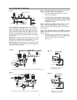
Step 3.  Run the steam supply line

 from the steam 

header to the humidi

fi

 er as indicated in Fig. 2-1. Observe 

the following:

A.  Take steam supply line from the top of the supply 

main – never from the side or bottom.  If several 
humidi

fi

 ers take steam from a single supply line, 

be sure to trap the end of the run-out with an Arm-
strong Trap of suitable size.  If the steam supply is 
very wet, install a drip pocket or separator ahead 
of the humidi

fi

 er.

B.  Size supply line in accordance with Table 2-1.  If 

the steam supply is 5 psi or less, it is advisable to 
use one pipe size larger and reduce the pipe size 
just ahead of the strainer and humidi

fi

 er.

C.  Pitch the supply line in the direction of 

fl

 ow.

Humidifi er Piping

D.  Expansion and Contraction.  With average length 

of supply line, the dimension change from hot to 
cold should not exceed 2”.  Provide piping with 3 
elbows to get swing to take care of expansion and 
contraction (See Fig. 2-2).

E.  Clean piping.  After running the supply line, blow 

down at full steam pressure to eliminate dirt and 
pipe cuttings.

F.  A Pipe Strainer is furnished with each humidi

fi

 er.  

Install (after blowing down supply line) as indi-
cated on drawing.

G.  Swivel connections may be desirable – see 
 

Fig. 2-2 and explanatory captions.

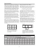
H.  Pressure Reducing Valve. If required refer to 

Fig. 3-1 and explanatory captions.

  Table 2-1 Recommended Pipe Sizes

Humidifi er 

Size

Supply  Header                                 

to Strainer

Steam  Inlet                                     

& Strainer

Drip      

Leg

Trap 

Piping

91

3/4”

3/4”

1”

3/4”

92

3/4”

3/4”

1”

3/4”

93

1-1/4”

1-1/4”

1-1/4”

3/4”

Steam Pipe Capacities

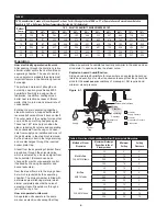
For computing ability of piping to deliver an adequate supply of steam to 

humidifi er. Capacities shown are in pounds per hour.

  Table 2-2 Steam Pipe Capacity at 5 psi

Pipe

Size in.

Pressure drop, psi per 100 ft. of pipe length

1/8

1/4

1/2

3/4

1

1

24

31

44

54

62

1-1/4

52

68

97

120

140

1-1/2

81

100

150

180

210

2

160

210

300

370

430

2-1/2

270

350

500

610

710

  Table 2-3 Steam Pipe Capacity at 15 psi

Pipe                    

Size in.

Pressure drop, psi per 100 ft. of pipe length

1/8

1/4

1/2

3/4

1

2

1

27

38

53

65

76

110

1-1/4

59

83

120

140

160

230

1-1/2

91

130

180

220

260

360

2

180

260

370

450

520

740

2-1/2

300

430

600

740

860

1210

  Table 2-4 Steam Pipe Capacity at 25 psi

Pipe                    

Size in.

Pressure drop, psi per 100 ft. of pipe length

1/8

1/4

1/2

3/4

1

2

3/4

15

21

30

37

43

60

1

30

43

61

75

86

122

1-1/4

67

95

130

160

190

260

1-1/2

100

140

210

250

290

410

2

210

300

420

510

590

840

2-1/2

340

490

690

850

980

1380

  Table 2-5 Steam Pipe Capacity at 50 psi

Pipe           


  Size in.

Pressure drop, psi per 100 ft. of pipe length

1/4

1/2

3/4

1

2

5

3/4

27

38

47

54

76

120

1

54

77

94

110

150

240

1-1/4

120

170

210

240

340

530

1-1/2

180

260

320

370

520

830

2

370

530

650

750

1060

1680

2-1/2

620

870

1070

1240

1750

2760

Figure 2-1.

Figure 2-2.

Strainer

Steam

Trap

Dirt

Pocket

Check

Valve

Take off top of
steam supply

To low
pressure return

Pitch down 1/2" in 10'

Typically pneumatically controlled humidifier installation.

Strainer

Steam

Trap

Dirt

Pocket

Check

Valve

To low
pressure return

Take off top of
steam supply

Pitch down 
1/2" in 10'

Swivel connections shown above permit direction of discharge
to be altered easily.  Loosen both unions, adjust direction, then
retighten unions.

Summary of Contents for AM-91A

Page 1: ...spring range is specified AM VSA Models AMEF AMAF FSA Models Figure 1 1 Figure 1 2 Dimensions Armstrong Area Humidifiers Fig 1 1 VSA AM models do not have fans Fig 1 2 FSA AMEF models have electrically operated fans AMAF models utilize air powered fans Installation Procedure B C D F J E H G C D F B J E Table 1 1 Model No B C D E F G H J AM 91A 15 15 16 3 3 8 3 13 16 6 1 16 3 1 16 13 1 4 AMAF 91A 1...

Page 2: ...1 1 4 1 1 4 1 1 4 3 4 Steam Pipe Capacities For computing ability of piping to deliver an adequate supply of steam to humidifier Capacities shown are in pounds per hour Table 2 2 Steam Pipe Capacity at 5 psi Pipe Size in Pressure drop psi per 100 ft of pipe length 1 8 1 4 1 2 3 4 1 1 24 31 44 54 62 1 1 4 52 68 97 120 140 1 1 2 81 100 150 180 210 2 160 210 300 370 430 2 1 2 270 350 500 610 710 Tabl...

Page 3: ...ve Relief Valve A pressure relief valve between the humidifier and pressure reducing valve is a good insurance Humidi fier bodies are only rated for 60 psig steam service Pressure Gage A pressure gage or connection for install ing a gage between reducing valve and the humidifier may save its cost many times over Air and Electrical Connections 10 Min Strainer Steam Trap Steam Trap Steam Supply Dirt...

Page 4: ...r size and type of units required and the location of both humidifier and humidity controllers Sizing and location with natural ventilation These are the average industrial humidification applications with Room temperatures 65 to 80 Relative humidities 35 to 80 Natural ventilation i e infiltration around windows and doors Selection Data Required Minimum Outdoor Temperature for most jobs figure 10 ...

Page 5: ...ges These can be determined from exhaust fan capacity where known The cu ft per hour capacity of the fans divided by the cubic feet of space to be humidified will give the number of air changes Where the capacity of fan or fans is not known air changes can be measured with velometer readings at all open doors elevator shafts etc leading to the room and with fans operating at full capacity Your Arm...

Page 6: ...on is through a jet nozzle or by a fan How air operated units work Air operated units operate in the same manner as electric units except that they Operation Figure 6 1 utilize a pneumatic humidistat as humidity controller in the space and an air operator to open and close the steam valve Explosion hazard humidification Sizing air operated humidifiers for areas where an explosion hazard ex ists is...

Page 7: ...with dirt 2 Return line pressure above humidifier pressure 3 Too much vertical lift 4 Wrong type of trap used 5 Second trap short circuiting the humidifier trap Operation and Servicing Humidifier Discharges Continuously Even though Humidity Has Reached Desired Level A Mechanical Trouble 1 Humidistat fails to open points frozen 2 Dirt holds solenoid plunger in open position 3 Bent solenoid tube hol...

Page 8: ...efects or any condition or use of the products supplied by Armstrong however caused and whether such claim is based upon warranty contract negligence strict liability or any other basis or theory is limited to Armstrong s repair or replacement of the part or product excluding any labor or any other cost to remove or install said part or product or at Armstrong s option to repayment of the purchase...

Reviews: