2
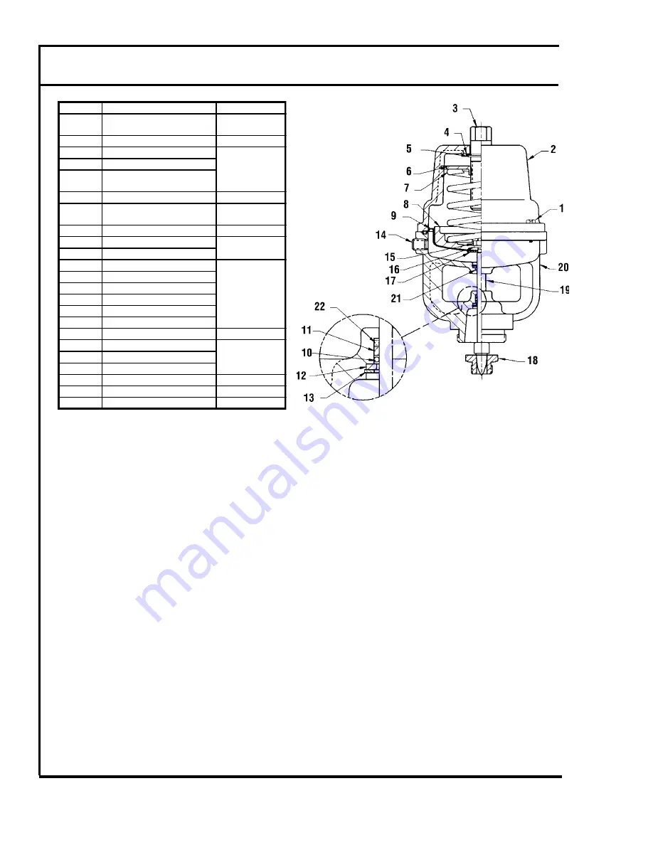
Repair and Adjustment Procedures for
C-1801 Pneumatic Operators
Number
Description
Part Number
1
Flange Hold Down Screws
#10-24 with washers
A-8956-A
2
Operator Cover
C-1800-C
3
Spring Adjusting Screw
A-8996 Set
4
Friction Washer
5
Spring Adjustment
Snap Ring
6
Spring Adjustment Disc
B-2358
7
Spring
A-6958 (10#)
A-6958-B (5#)
8
Piston
B-2360-C
9
Diaphragm
A-9330
17
Flat Washer
10
Spring Loaded Stem Seal
A-8991
Seal Kit
11
Brass Seal Spacer
12
Seal Retaining Washer
13
Seal Retaining Ring
21
Upper Quad Ring
22
Lower Quad Ring
14
1/8" NPT Pipe Plug
A-6000-C
19
Valve and Seat Assembly
See Chart 1130
15
Hex Nut
16
Lock Washer
18
Valve Seat
See Chart 1130
20
Operator Base (91, 92, 93)
C-1799-F
20
Operator Base (90)
C-1799-H
B. DISASSEMBLING THE ARMSTRONG C-1801 PNEUMATIC OPERATOR
Most subsequent repair procedures require disassembly of the operator.
1. Turn the spring adjusting screw (3) clockwise until it moves freely.
2. Remove the four flange screws (1).
3. Remove the operator cover (2).
4. Remove the spring adjusting screw (3), spring adjusting disc (6), snap ring (5), and fric-
tion washer (4).
5. Remove the spring (7).
C. REPLACING THE VALVE AND SEAT
ALWAYS
replace the valve and seat as a set.
1. Remove operator in accordance with Section A.
2. Using a socket wrench, remove the old valve seat (18) from the body and install a new
one.
3. Disassemble the pneumatic operator in accordance with Section B.
4. Place an
¹⁄₈
" allen wrench in the end of the valve & stem assembly (19). Hold the valve
stem in position with the allen wrench while removing the hex nut (15) with a
⁷⁄₁₆
" wrench.
5. Remove washer (16).
6. Remove valve and stem assembly (19) and replace with the new one.
7. Replace the washer (16) and the hex nut (15). Tighten the nut.
8. Assemble the operator in accordance with Section G.
Figure 2-1


