North America • Latin America • India • Europe / Middle East / Africa • China • Pacific Rim
armstrong
international.com
Designs, materials, weights and performance ratings are approximate and subject to change without notice. Visit
armstrong
international.com for up-to-date information.
15
Installation
Step 1 - Placing and wall attachment
MODEL EHU-801: Making sure the unit is level, hold it against the mounting surface and mark the whole pattern. Attach the
units to studs or other sturdy structure with the two 3/8”× 1½” lag screws provided.
MODELS EHU-803 & 804: Making sure the mounting bracket is level; attach it to studs or other sturdy structure with the two
3/8”× 1½” lag screws provided. Hang the humidifier on the mounting bracket.
Step 2 - Water connection
FILLING: Connect the unit to the building water supply (25 to 125 psig pressure). Install a shut-off valve near the humidifier.
Connect the water supply to the 3/8” tube compression fitting on the fill valve adaptor.
NOTE:
ORDINARY (POTABLE) TAP WATER IS RECOMMENDED. IF
POTABLE WATER IS NOT AVAILABLE, CONSULT THE FACTORY
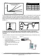
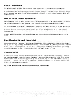
DRAINAGE: Connect to a suitable waste draining system. Use the
clear drain hose provided and a 1” copper pipe, pitched 1” per foot.
The drain water may be as hot as 160°F (70°C). Drain it where it will
not present a hazard to personnel. An air gap to prevent backflow is
required. If drain water is required to be less than 140°F (60°C), use
of Temp-R-Drain will be required.
WARNING!
When unit is draining, burn hazard exists at the drain outlet
Human bodies or other articles that are not resistant to high
temperature should keep away from contacting or getting near this place. Negligence of this warning might result in the loss
of property or personal damage.
Step 3 - Steam pipe positioning
Verify that the proper length and type of steam dispersion tube has been selected for proper dispersion tube lengths.
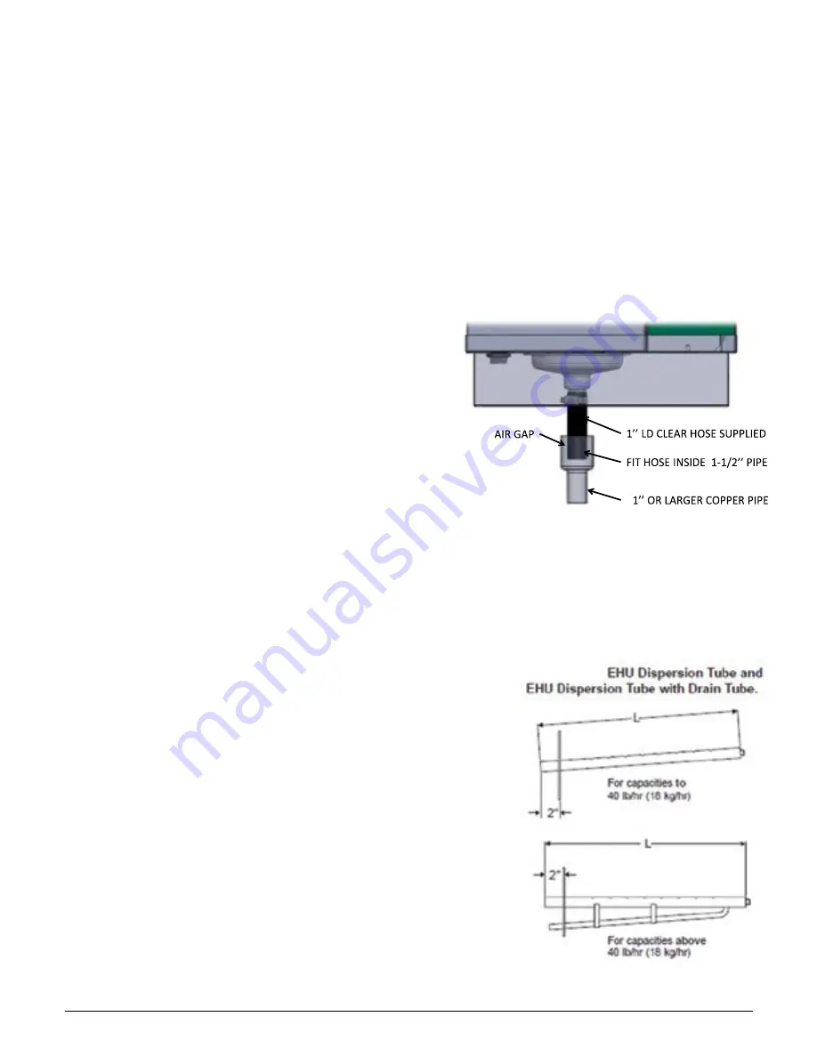
The low capacity dispersion tube is sloped toward the generator to allow for gravity drainage. On applications where the
humidifier output capacity is greater than 40 Ibs/hr (18kg/hr), a high capacity
tube with a ½”O.D. drain tube must be used. Drain tube must have minimum
6” water seal.
Select a location on the duct that provides adequate length for vapor mixing,
the shortest connection length for vapor mixing, and the shortest connection
length to the humidifier. Preferably the location should be 6” downstream
and/or 10 feet upstream from any dampers, vanes, bends in the duct, or
controllers (i.e. high limit stat). Do not install the dispersion tube into ducts
in which airflow exceeds 2,000 fpm (10 m/s). Do not restrict airflow in ducts
with a depth of 8 inches or less. Avoid placing manifold in downward, high
velocity air flow as dynamic air pressure will restrict steam flow. Use the
template provided to cut installation holes in the duct for the dispersion tube
as in. Refer to Figure 17-2 and 17-3.
Insert the dispersion tube into the duct so the holes face upward. Fasten
the mounting plate to the outside of the duct with sheet metal screws. If the
dispersion tube is 36” long or more, support the far end with threaded rod or
similar means.
Figure 16-1
Figure 16-2


