North America • Latin America • India • Europe / Middle East / Africa • China • Pacific Rim
armstrong
international.com
Designs, materials, weights and performance ratings are approximate and subject to change without notice. Visit
armstrong
international.com for up-to-date information.
14
Vertically Vented Humidifier
The humidifier may be vented vertical but it should be done with as straight and short of a run as possible
and in all cases must be within the stated minimum and maximum vent lengths of 10' to 100'.
When vented vertical it may vent into a chimney when the above rules are followed concerning lining; or it
may use a listed Category III vent with a UL listed wind cap at the termination above the roof.
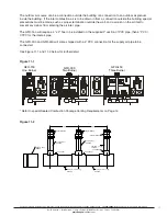
Figure 14-1
Sealed Combustion Package Venting Requirements
Sealed combustion can be used with horizontal or vertical venting, but the intake and exhaust must be
located in the same pressure zone. See Figure 14-1 for mounting configuration.
Steam Distribution
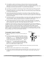
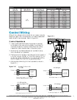
1. The dispersion tube should be proper length. Verify correct size from Table 14-1.
2. Install dispersion tube horizontally in duct so holes face upward. Air flow must be vertical up or horizontal.
Do not restrict duct with a height of 8" (20 cm) or less. Installations over 2000 FPM (10 m/s) air velocity
are not recommended. Consult factory if air flow is vertical down or air velocity is over 2000 FPM (10 m/s).
Do not install in ducted systems with static pressure exceeding 6” WC (15 cm).
3. The dispersion tube should be located upstream of a straight duct run, without obstructions, 10 feet (3 m)
or more in length. Consult the factory if this distance is not available.
4. Use the template provided to cut dispersion tube installation holes. Fasten the mounting plate to duct with
sheet metal screws. If the dispersion tube is 36" (91 cm) or longer, support the far end with threaded rod
or similar means.
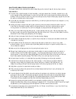
5. The dispersion tubes should be connected to the GFH tank using copper pipe (stainless steel for DI units).
The pipe size of the steam run should correspond with the nominal pipe size of the steam outlet on the
generator. Hose cuffs are provided with the unit to connect to the steam supply piping. Pitch pipe back
to unit 1” (2.5 cm) per foot. The steam pipe must be free of kinks and sags to allow for gravity drainage of
condensate. Maximum pipe run distance from tank to dispersion tube is 40 feet (12 m) equivalent piping
length. Avoid excessive use of elbows or 45° changes in direction. A “P” trap drain should be installed
every 20 feet (6 m) of piping run or at the bottom of vertical runs that cannot drain back to the tank. See
Fig. 5-1 for “P” trap detail.
Alternative for shortened non-wettable vapor trail
For applications with particularly limited downstream absorption distance, Armstrong HumidiPack may be
considered. HumidiPack is a prefabricated separator/header and multiple dispersion tube assembly. It
provides uniform distribution and shortened non-wetting vapor trail. Consult Armstrong Installation Bulletin
No. 560 for more information.
45 °
45 ° Elbow
Flue Vent
12" Min.
18" Min.
11" Min.
9" Min.
Vane
Air Intake
4" Coupling
4" Combustion Air Terminal
18" Min.
18" Min.
45 °
Air Intake
For Right Handed Flue Vent
For Left Handed Flue Vent

