North America • Latin America • India • Europe / Middle East / Africa • China • Pacific Rim
armstrong
international.com
Designs, materials, weights and performance ratings are approximate and subject to change without notice. Visit
armstrong
international.com for up-to-date information.
15
Armstrong C-1471 & C-1472
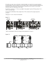
1.9 - 3.9 Vdc
Voltage Source 5
27
26
28
Green
Black
White
Ground
Set Stat Input Jumper to 1.9 - 3.9 Vdc (J5)
Set Stat Voltage Jumper (J6) to 12 VAC
0 - 10 VDC other than
Armstrong Standard Stat
Part No.
C-1471
or
C-1472
0 - 10 VDC
Controller
Stat In
Voltage Source 5
27
26
28
Ground
Set Stat Input Jumper to 0 - 10 Vdc (J2)
Stat In
Voltage Source
0 - 5 VDC
Controller
4 - 20 mA
Controller
5
27
26
28
Ground
Set Stat Input Jumper to 0 - 5 Vdc (J3)
Set Stat Input Jumper to 4 - 20 mA (J4)
0 - 5 Vdc Signal
4 - 20 mA Signal
Stat In
Voltage Source 5
27
26
28
Ground
Stat In
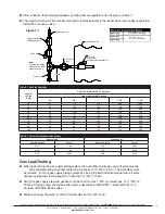
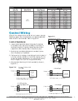
Table 14-1
Series GFH
and GFH-DI
Series GFH and
GFH-DI "DL" Dia.
Steam Dispersion
Tube Length (mm)
Duct Width
Min. (mm)
Max. (mm)
DL-1
2-3/8"
(60 mm)
12" (305")
11" (279)
16" (406)
DL-1.5
18" (457)
17" (432)
22" (558)
DL-2
24" (610)
23" (584)
34" (863)
DL-3
36" (914)
35" (889)
46" (1168)
DL-4
48" (1220)
47" (1194)
58" (1473)
DL-5
60" (1524)
59" (1499)
70" (1778)
DL-6
72" (1829)
71" (7803)
82" (2082)
DL-7
84" (2134)
83" (2108)
94" (2387)
DL-8
96" (2438)
95" (2413)
106" (2692)
DL-9
108" (2743)
107" (2718)
118" (2997)
DL-10
120" (3048)
119" (3022)
130" (3302)
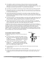
Figure 15-2
Figure 15-1
Voltage Source
26
27
28
24
25
A9023
Fan Interlock or
Pressure Switch
5
6
4
A18609
or
A18610
0-10 Vdc
Stat
(Standard)
A8581
High Limit
Humidistat
5
Stat Out
Stat In
Ground
Sail / Inter.
Ground
Note:
All Switches Are Open on Fault Type.
Set Voltage Source Jumper to 24 VAC. Set Jumper to 0-10 VDC
Control Wiring
Wiring for low voltage controls should not run in same conduit as
the power supply. Use of shielded wire or a separate dedicated
metal conduit is recommended. Refer to Figure 15-1.
Control Humidistat
1. Locate control humidistat where it will sense the average
air condition of the space to be humidified. Avoid areas of
restricted circulation or locations where the sensor will be
subjected to drafts, localized heat or moisture sources.
2. Optional duct mounted humidistats are available to sense
return or exhaust air, if preferred.
3. The Series GFH is capable of operating with control signals of
0-10 Vdc, 4-20 mA, 0-5VDC or 1.9-3.9 Vdc. See Fig. 15-1 for
location of switches and Table 21-1 for correct switch setting.
Refer to Figures 15-1 and 15-2 for appropriate wiring.
4. Wire standard Armstrong 0-10 Vdc humidistat as shown in
Figure 15-1.
*Minimum of two tubes must be used.

