North America • Latin America • India • Europe / Middle East / Africa • China • Pacific Rim
armstrong
international.com
Designs, materials, weights and performance ratings are approximate and subject to change without notice. Visit
armstrong
international.com for up-to-date information.
16
Fan Interlock Switch
A fan interlock switch is recommended to deactivate the humidifier when there is insufficient air flow in a
duct system. A duct pressure switch is preferred as a fan interlock device. The pressure switch should open
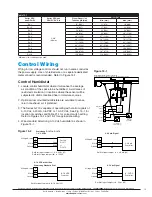
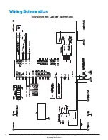
on insufficient air flow (opens on fault). See Figure 15-1 for wiring terminals and overall wiring diagrams.
Complete installation and wiring instructions are contained in the duct pressure switch package. Armstrong
Pressure Switch: (Armstrong Part A9023) All Pressure and electrical connections and set point adjustments
are on side for each installation. Temperature limit: 32°F. to 180°F. Maximum surge pressure: 10 psig Rated
pressure: 45" H
2
O Pressure connections: 1/8" NPT Operating range: 0.07 to 0.15" H
2
O
Installation
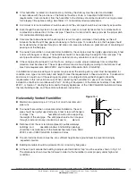
a. Select a location that is free from excessive vibration, corrosive atmosphere and within temperature
limitations.
b. Connect switch from pressure source with tubing (1/4" O.D. is recommended) to high pressure port. The
low pressure port is left open to atmosphere.
Note
: Above procedure is for downstream side of fan installation. For fan suction side installation, see
instructions accompanying switch.
c. Electrical connections to the switch are provided by means of screw terminals marked common and
normally open. The normally open contacts close when pressure increases beyond the set point.
d. Complete instructions are contained in the pressure switch package.
Note: Limit switches (high limit and fan interlock switches) open on fault.
Alarm Circuit
The connections labeled REM ALM on the TB6 connector on PC board, are connections for a class II NEC
alarm circuit (switch closure only, 1 amp. maximum 24 Vdc or 0.5 amp. @ 125 Vac). The switch will close
when the error or service LEDs are energized.
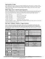
Stat Voltage
Jumper Default
to 24vAC
Stat Input
Jumper Default
0-10v J2
Drain Freq SF 0
Drain Freq SF 1
Drain Freq SF 2
EOL Time 0
EOL Time 1
EOL Time 2
Drain Time SF 0
Drain Time SF 1
Drain Time SF 2
D/A Scale 1
D/A Scale 2
Com Addr 0
Com Addr 1
Prod Test/Run
Test/Run
DS/Keypad
Figure 16-1
High Limit Humidistat
A duct mounted High Limit Stat (Armstrong Part A8581) is recommended as a precaution against localized
saturation in the duct. It is an on-off controller that opens the contact on a rise in humidity (opens on fault).
See Figure 15-1 for wiring terminals and overall wiring diagrams.
It should be mounted 6 to 10 feet downstream from the steam dispersion tube (see Fig. 15-1). The high limit
stat must be upstream of filters, silencers, takeoffs, etc. since these devices can reduce duct humidity and
prevent the high limit stat from doing its job. Complete mounting instructions are contained in the High Limit
Stat package.


