background image

North America  •  Latin America  •  India  •  Europe / Middle East / Africa  •  China  •  Pacific Rim

armstrong

international.com

Designs, materials, weights and performance ratings are approximate and subject to change without notice.  Visit 

armstrong

international.com for up-to-date information.

27

1.  Turn the Steam Generation switch to the off position to drain the tank completely. 
2.  Tun off gas, electricity and water supply to the unit. 
3.  Using a vacuum, remove all dust from the control cabinet area, and blower assembly. 
4.  Disconnect the gas piping going to the gas valve. 
5.  Disconnect wiring harness to the blower assembly.
6.  Unplug wires to blower and pressure switch.
7.  Unplug flame detection rod and ifniter wires from module. 
8.  Remove the 4 bolts holding the blower assembly to the heat exchanger and remove the burner assembly. 
9.  Disconnect steam distribution piping from lid of unit, and remove lid from unit.
10.  Disconnect Vent piping from exhaust nipple, or exhaust collection box.

11.  Remove either exhaust nipple or exhaust collection boxby removing all the bolts holding it in place.  Care  

should be taken not to damage the gasket. 

12.  Remove the 12 bolts holding the front of the heat exchanger in place, and remove any additional bolts holding 

the exhaust end of the heat exchanger in place. 

13.  Carefully lift the heat exchanger from the steam generation chamber.

14.  The new heat exchanger will ship in two gaskets (shipped loose) for the inlet and exhaust connections of the  

heat exchanger.  Remove adhesive strips, and install gaskets on appropriate surfaces of the heat exchanger.

15.  Carefully lower the heat exchanger into position in the steam chamber.

16.  Install all required bolts into position in both the inlet and exhaust sides of the heat exchanger.  In the case of 

the GFH-150, the exhaust nipple must be installed prior to bolting the exhaust end of the heat exchanger   
in place.

17.  Snug all 12 bolts on the inlet side of the heat exchanger, and all 8 bolts on the exhaust end of the heat  


exchanger.

18.  Using Figure 27-1 torque all bolts to 50 in-lb in the order shown.  Using the same torque pattern, continue to  

torque all the bolts to the inal 70 in-lb torque rating.

19.  VERIFY ALL BOLTS GET TORQUED PROPERLY ON BOTH THE INTAKE AND EXHAUST ENDS OF THE  

HEAT EXCHANGER.

20.  Replace the exhaust collection box.  The gasket used between the tank and the exhaust collection box does 

not have adhesive gasket, so care will have to be taken to make sure the gasket is in proper place.

21.  Re-connect the exhaust vent piping to exhaust collection box, or exhaust nipple. 
22.  Re-install steam chamber lid, and re-connect steam distribution piping. 

23.  Re-install gasket, and burner assembly into heat  

exchanger. Inspection of the gasket will be required if old gasket can be used, or should be replaced.


24.  Re-connect gas supply line, turn gas on and check for leaks. 


25.  Re-connect all control wiring.


26.  Apply power and turn Steam Generation switch to ON  

position.

27.  Verify normal operation outlined in Start-Up Section. 

Removing / Replacing Heat Exchanger

8

10

12

1

3

5

7

9

11

2

4

6

2

7

5

3

1

8

6

4

Figure 27-1

Summary of Contents for Gas Fired HumidiClean Series

Page 1: ...548 EN Armstrong Series GFH Gas Fired HumidiClean GFH 150 GFH 300 and GFH 450 Category I III Gas Fired Appliance Installation and Maintenance Manual Please read and save these instructions...

Page 2: ...other appliance WHAT TO DO IF YOU SMELL GAS Do not try to light any appliance Do not touch any electrical switch so do not use any phone in your building Immediately call your gas supplier from a nei...

Page 3: ...ng 9 Combustion Air 10 Venting General 12 Horizontally Vented 13 Vertically Vented 13 Steam Distribution 14 Control Wiring 15 Control Humidistat 15 High Limit Humidistat 15 Air Flow Pressure Switch 16...

Page 4: ...and any gas control that has been under water Do not lift humidifier by gas controls gas manifold firebox or control panel This unit should only be lifted by cross beams between the support legs Shoul...

Page 5: ...llow the instructions concerning combustion and ventilation air The humidifier should be located in an area where leakage from the tank or its connections will not result in damage to the adjacent str...

Page 6: ...om for up to date information 6 A T U F J P N H K C V D E S L G B T A F N J P K H M W S L G B E D C Figure 6 1 Model 150 T A U F J P N H K S L D V C E G B Figure 6 2 Model 300 Figure 6 3 Model 450 Mou...

Page 7: ...et Spacing 12 305 16 406 V Vent Outlet to Front of Cabinet 47 7 8 1216 51 7 8 1317 W Gas Inlet to Edge of Tank 7 1 4 84 Water Inlet 3 8 NPT 10 3 8 NPT 10 3 8 NPT 10 Drain Connection 3 4 20 3 4 20 3 4...

Page 8: ...AN CGA B149 in Canada Do not use flexible connectors Piping to unit should conform with local and national requirements for type and volume and gas handled and pressure drop allowed in line Refer to T...

Page 9: ...ne Note All piping and fittings external to humidifier supplied by others Drip Pocket 3 Min Ground Joint Union Humidifier Cabinet Gas Cock Supplied by Armstrong International Inc Figure 9 1 Allow at l...

Page 10: ...any openings on the appliance spaces around the appliance or air openings adjacent to the appliance area Do not block the flow of combustion or ventilation air Openings must be provided for necessary...

Page 11: ...wall and a screen on the air inlet to prevent any debris from entering the air inlet pipe The GFH 150 will require a 4 x 2 Tee to be installed on the supplied 2 section of PVC pipe then 4 PVC CPVC for...

Page 12: ...brand of vent pipe The vent material manufacturer s instructions for vertical venting must be followed If vent pipe is being installed in an existing chimney have chimney inspected for blockages and...

Page 13: ...elbows should be used and the vent pipe should be run as directly as possible Even though the vent system to be used is stainless steel care must be taken that no condensate from combustion be allowed...

Page 14: ...of a straight duct run without obstructions 10 feet 3 m or more in length Consult the factory if this distance is not available 4 Use the template provided to cut dispersion tube installation holes F...

Page 15: ...71 7803 82 2082 DL 7 84 2134 83 2108 94 2387 DL 8 96 2438 95 2413 106 2692 DL 9 108 2743 107 2718 118 2997 DL 10 120 3048 119 3022 130 3302 Figure 15 2 Figure 15 1 Voltage Source 2 6 2 7 2 8 2 4 2 5...

Page 16: ...installation see instructions accompanying switch c Electrical connections to the switch are provided by means of screw terminals marked common and normally open The normally open contacts close when...

Page 17: ...st systems or in any location where potentially flammable vapors or liquids could be taken in to the combustion chamber Remove unit from shipping skid prior to locating final position of unit Please c...

Page 18: ...m Designs materials weights and performance ratings are approximate and subject to change without notice Visit armstronginternational com for up to date information 18 Gas Fired Roof Installation Air...

Page 19: ...nginternational com for up to date information 19 GFHE 150 Outdoor Enclosure Flue Piping Access Flue Piping Access Combustion Air Intake Vent Removable Access Door Water and Electric Inlet Gas Line In...

Page 20: ...ginternational com for up to date information 20 GFHE 300 Outdoor Enclosure 44 3 8 1052 mm 61 1549 mm 66 1 8 1680 mm 41 7 8 1064 mm 62 1575 mm Flue Piping Access Air Intake Vent for Electronics Lid St...

Page 21: ...l com for up to date information 21 GFHE 450 Outdoor Enclosure 57 5 8 1465 mm 66 1 8 1680 mm 61 1550 mm 55 1 8 1400 mm 62 1575 mm Lid Flue Piping Access Steam Outlet Access Electronics Access Door Air...

Page 22: ...gin to fill When the water level reaches the low level control electrode the unit will perform its precombustion checks 9 After the precombustion checks are done the unit will run at 100 for a period...

Page 23: ...nk with water when the low water level is reached These fill intervals will be started as defined in the software of the printed circuit board and be shut off by the high water switch The PC Board gen...

Page 24: ...N section after the Gas Fired HumidiClean has accumulated 90 of the selected Service Life in hours of heater on time the SERVICE LIFE LED will flash blink At this time the ionic beds in the tank shoul...

Page 25: ...igh Water Electrode Probe To Top of Tank Reducing Bushing Figure 25 1 Modify the Bed Life Setting 1 Complete the steps for servicing the unit as outlined above 2 The unit must run for at least an hour...

Page 26: ...ove the 4 bolts holding the blower assembly to the heat exchanger and remove the burner assembly 10 Use a 6 flue brush with a 28 extension and a reversible drill Work brush in and out of the fire tube...

Page 27: ...onnections of the heat exchanger Remove adhesive strips and install gaskets on appropriate surfaces of the heat exchanger 15 Carefully lower the heat exchanger into position in the steam chamber 16 In...

Page 28: ...time Check Debris in fill valve no water flow or low water pressure drain valve leaking or stuck open defective low water switch electrodes need cleaning 3 Blinks The high level switch did not close...

Page 29: ...ll last approximately 2 seconds 1 Flash then pause System lockout 2 Flashes then pause Pressure switch stuck closed 3 Flashes then pause Pressure switch stuck open 6 Flashes then pause 115 Volt AC pow...

Page 30: ...China Pacific Rim armstronginternational com Designs materials weights and performance ratings are approximate and subject to change without notice Visit armstronginternational com for up to date inf...

Page 31: ...China Pacific Rim armstronginternational com Designs materials weights and performance ratings are approximate and subject to change without notice Visit armstronginternational com for up to date inf...

Page 32: ...East Africa China Pacific Rim armstronginternational com Designs materials weights and performance ratings are approximate and subject to change without notice Visit armstronginternational com for up...

Page 33: ...East Africa China Pacific Rim armstronginternational com Designs materials weights and performance ratings are approximate and subject to change without notice Visit armstronginternational com for up...

Page 34: ...urope Middle East Africa China Pacific Rim armstronginternational com Designs materials weights and performance ratings are approximate and subject to change without notice Visit armstronginternationa...

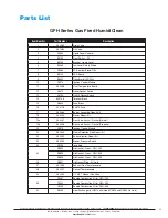
Page 35: ...r Switch 14 B2414 3 Terminal Block 15 A8649 Fuse Block 16 A10718 3 AMP Fuse 17 A22460 Burner Assembly Repair Kit 18 A22459 Blower Repair Kit 19a A22457 Gas Valve Assy w Gasket Natural 19b A22458 Gas V...

Page 36: ...ligence strict liability or any other basis or theory is limited to Armstrong s repair or replacement of the part or product excluding any labor or any other cost to remove or install said part or pro...

Reviews: