North America • Latin America • India • Europe / Middle East / Africa • China • Pacific Rim
armstrong
international.com
Designs, materials, weights and performance ratings are approximate and subject to change without notice. Visit
armstrong
international.com for up-to-date information.
29
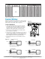
Dip Switch Settings / Jumpers / Toggle Switches
There is a bank of DIP switches on the top edge of the PC board. The drain frequency and duration (drain
time) and the Service Life time setting can be modified. Several other parameters are also adjustable. The
main power must be turned off before the DIP switches are changed. See chart below for a complete listing of
DIP switch settings. Please consult factory if unsure regarding any DIP switch setting. See Fig. 16-1 on page
16 for locations.
Clearing Error Codes
After troubleshooting, the error state must be cleared by depressing the reset button for 10 seconds. All the
LED's will then flash. Release the reset button and the unit should resume normal operation (it will fill or drain
to get to the low level switch then fill to the high and begin boiling). Turning the unit on and off will not clear
most of the error states.
White-Rogers Gas Control Board Diagnostics
When the unit experiences a burner error the White Rogers board will show blink code in the bottom left hand
corner of the board in the form of a red LED. The blink code will only show for 2 minutes after the unit has
gone into error. Each flash will last 0.25 seconds and each pause will last approximately 2 seconds.
1 Flash, then pause ........................System lockout
2 Flashes, then pause ....................Pressure switch stuck closed
3 Flashes, then pause ....................Pressure switch stuck open
6 Flashes, then pause ....................115 Volt AC power reversed
7 Flashes, then pause ....................Low flame sense signal
8 Flashes, then pause ....................Check igniter or improper grounding
Continuous flashing, (no pause) .....Flame has been sensed when no flame should be present (no call for heat)
The LED will also flash once at power-up.
Table 29-1. Circuit Board Dip Switch Settings
Dip Switch 1
Parameter
Drain On Time
2 Min.
5 Mins.
10 Mins.
15 Mins.
SB1-1 (2)
Drain Time
Not Used
SB1-2 (1)
Off
Off
On
On
SB1-3 (0)
Off
On
Off
On
End Of Life
500 Hrs.
1000 Hrs.
2000 Hrs.
3000 Hrs.
SB1-4 (2)
End of Life
Not Used
SB1-5 (1)
Off
Off
On
On
SB1-6 (0)
Off
On
Off
On
Drain Frequency
1 Hr.
4 Hrs.
12 Hrs.
24 Hrs.
SB1-7 (2)
Drain
Frequency
Not Used
SB1-8 (1)
Off
Off
On
On
SB1-9 (0)
Off
On
Off
On
Dip Switch 2
Parameter
DS / Keypad
SB2-1
Keypad
Not Used
Production Test
SB2-2
Test / Run
Off = Run On = Test
SB2-3
Prod Test /
Run
Off = Run On = Test
Comm. Address
SB2-4 (1)
Comm
Address
Not Used
SB2-5 (0)
Not Used
D/A Scale
SB2-6 (2)
D/A Scale 2
Not Used
SB2-7 (1)
D/A Scale 1
Not Used
Voltage Source (J2)
5 Vdc
Supplies 5 Vdc to Voltage Source terminal on low
voltage term. strip
24 VAC
Supplies 24 VAC to Voltage Source terminal on low
voltage term. strip
12 VAC
Supplies 12 VAC to Voltage Source terminal on low
voltage term. strip
Stat Input
Set Jumper According to Stat Input
J3
1.9 - 3.9 Vdc Stat Input
J4
4 - 20 mA Stat Input
J5
0 - 5 Vdc Stat Input
J6
0 - 10 Vdc Stat Input
Manual
Switches
Manual Switch Actuates: (Normal position is Up,
Down to Activate)
SW-1
Fill Valve
SW-2
Drain Valve
SW-3
Temper Valve (Not Used)

