10
Start-Up Procedure
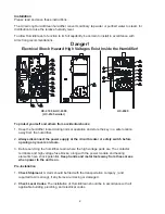
Before turning on the power:
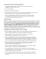
1. Examine the electrical compartment for any loose or disconnected component wiring.
Check all high voltage screw terminal connections at contactor, terminal strip, fuse block
& power module for tightness.
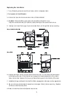
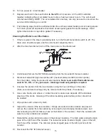
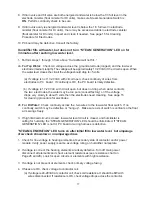
2. Open side door (HC-4100, 4145, 4300). Remove tank access panel by unscrewing
two black knobs. Make sure all beds are fastened securely to mounting pins. Position access panel
on tank making sure the gasket is in place and tighten two black knobs
(seven on HC-4500).
Note: Ionic beds not used on DI/RO units.
3. Check and recheck incoming voltage source and control wiring for proper connections
and tightness of connections.
4. Turn on water supply and check for leaks.
5. Make sure access doors and panels are secure.
Principle of Operation
The HumidiClean humidifier converts ordinary tap water or purified water to steam for distribution to
raise the relative humidity level. The demand for humidity is sensed by a humidistat which sends a
control signal to HumidiClean. HumidiClean is connected to the power supply (either 208, 240, 380, 480
or 600 Vac) through a separate circuit breaker supplied by the customer. When power is initially
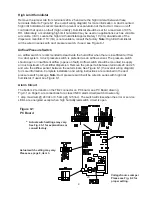
supplied to the unit from the circuit breaker, all LEDs will illuminate for 5 seconds. The “POWER” LED
will remain on and the unit’s fill valve solenoid is energized to allow water to enter the tank at a rate of
.31 gal/min (HC4500 fill rate is 2 gallons per minute). Note: If the water level in the tank is above the low
water level when power is applied, the drain valve will be energized to drain the water below the low
water level. Once the water level in the tank has reached the low water switch, assuming the air proving
switch is closed, the steam generator switch is on, and the high limit humidity switch is closed, the
heating elements will be activated and the “STEAM GENERATION” LED will be turned on.
The water fill solenoid continues to be activated until the water level in the tank has energized the high
water switch. Note: If fill or drain valves are not energized when power is first applied, check display
LEDs for diagnostic code. See DIAGNOSTICS section. The heating elements will remain on for 3
minutes to preheat the water inside the tank. During this preheat cycle the amperage draw of the tank
can be checked with a clamp on amp meter. The amperage draw on all high voltage wires connected to
the main power supply terminal block should correspond to the value on the nameplate.
After the 3 minute heat-up time, the HumidiClean will continue to produce steam based on the
demand signal from the humidistat. If the demand signal drops below 2% or the high limit/sail switch
circuit opens, the contactor(s) will open and the “STEAM GENERATION” LED will turn off. Note: If the
humidifier shut off due to low humidistat demand, a demand signal of 10% or greater is needed to re-
close the contactor and turn on the “STEAM GENERATION” LED. If all the signals are consistent as
stated above, HumidiClean will produce steam continuously and refill the tank with water when the low
water level is reached. These fill intervals will be started as defined in the software of the printed circuit.
Power to the heating elements is switched on and off by the triacs in the power module to
achieve a modulating output based on the signal demand from the humidistat. The triac utilizes a
1/2 second cycle time. For example, with a 50% humidistat demand signal the triacs would be on for
1/4 second and off for 1/4 second. If the triacs are fully on, the green “LOAD” LED on the power
module will be on constantly. When the triacs start to modulate (switch power to the heating
elements on and off) the LED will show the triac on condition and will appear to flicker or blink.


