16
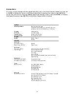
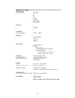
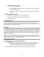
Enter Password ARMH
Run Mode
Run (Default)
Test
Contactor Count
1
2
3
4
Control Type
PWM (Default)
On/Off
Power Settings
1000 W
3000 W
5000 W
6650 W
8000 W
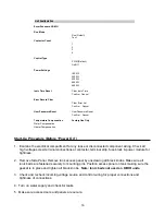
Ionic Time Reset
Clear Ionic Time
Confirm Cancel
Error Record Clear
Clear Error List
Confirm Cancel
User Password Reset
User Password Reset
Confirm Cancel
Temperature Compensation
Factory Use Only
Water Compensation
Heater Compensation
Unit Configuration
Start-Up Procedure (Before “Power On”)
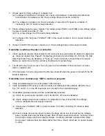
1. Examine the electrical compartment for any loose or disconnected component wiring. Check all
high voltage screw terminal connections at contactor, terminal strip, fuse block & power module for
tightness.
2. Remove Side Panel. Remove tank access panel by unscrewing all black knobs. Make sure all
ionic beds are fastened securely to mounting pins. Position access panel on tank making sure the
gasket is in place and tighten all black knobs.
Note: Ionic beds not used on DI/RO units.
3. Check and recheck incoming voltage source and control wiring for proper connections and
tightness of connections.
4. Turn on water supply and check for leaks.
5. Make sure access doors and panels are secure.
Summary of Contents for HumidiClean HC-6100 Series
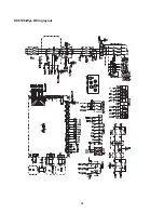
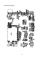
Page 28: ...HC6100 Wye Wiring layout 28...
Page 29: ...HC6100 Delta Wiring layout 29...
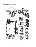
Page 30: ...30 HC6100 PAR Single Phase Wiring Layout...
Page 31: ...HC6300 Wye Wiring layout 31...
Page 32: ...HC6300 Delta Wiring layout 32...
Page 33: ...HC6500 Wye Wiring layout 33...
Page 34: ...HC6500 Delta Wiring layout 34...
Page 35: ...35 HC6500 WYE 2 contactors Wiring Layout...
Page 36: ...36 HC6500 Delta 2 contactors Wiring Layout...
Page 37: ...HC6700 Wye Wiring layout 37...


