50
Knock-Out for
Humidistat
1” Drain
Electrical
Supply
Knock-Out for
Humidistat
A
H
G
B
J
K
E
D
M
L
R
H
C
F
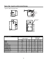
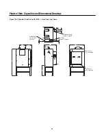
Physical Data, Capacities and Dimensional Drawings
Figure 49-1. Models HC-6100 and HC-6300
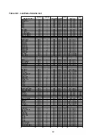
Table 134-1. Physical Data
Inches
mm Inches
mm
"A"-Width
21-15/16
557
26
660
"B"-Height
32-1/16
814
56-3/18
1428
"C"-Depth
22-1/3
576
32-3/32
815
"D"-Drain - Back
20
508
29-3/16
748
"E" Drain - Side
9-1/8
232
11-1/2
293
"F"-Steam Discharge Tube
2-3/8
60
2-3/8
60
"G"-Steam Outlet - Side
7-1/2
190
9-1/2
241
"H"-Steam Outlet - Front
14-1/3
364
12-7/8
328
"J"-Supply Water - Bottom
1-27/32
47
1-7/8
47
"K"-Water Supply - Front
2-13/32
61
2-3/8
60
"L"-Electrical Supply - Side
18
457
22-1/16
560
"M"-Electrical Supply - Back
10-3/16
254
16-1/4
413
"Q"-Steam Dispersion Outlets
—
—
12-3/16
310
Water Supply Connection
3/8 compression fitting
10
1/2 compression fitting
12
HC-6100 and HC-6300
HC-6500, HC-6700
and HC-6700DI
Summary of Contents for HumidiClean HC-6100 Series
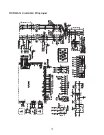
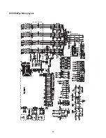
Page 28: ...HC6100 Wye Wiring layout 28...
Page 29: ...HC6100 Delta Wiring layout 29...
Page 30: ...30 HC6100 PAR Single Phase Wiring Layout...
Page 31: ...HC6300 Wye Wiring layout 31...
Page 32: ...HC6300 Delta Wiring layout 32...
Page 33: ...HC6500 Wye Wiring layout 33...
Page 34: ...HC6500 Delta Wiring layout 34...
Page 35: ...35 HC6500 WYE 2 contactors Wiring Layout...
Page 36: ...36 HC6500 Delta 2 contactors Wiring Layout...
Page 37: ...HC6700 Wye Wiring layout 37...

