3
Product Information
Operation
Bimetallic type steam traps employ the temperature effect of a thermostatic bimetallic element. At start up, the steam traps
have the ability to handle large condensate loads while the system is heating up. At this point the bimetallic element is
contracted and the valve is fully open removing condensate and non-condensable gases from the system. When the system
reaches steam temperature, the high temperature causes the bimetallic element to expand, pulling the valve stem to close
the valve. The valve remains closed until enough condensate backs up cooling the bimetallic element. As the bimetallic
element cools, the valve slightly opens to pass condensate and vent non-condensable gases. When steam temperature is
achieved, the valve closes again.
Product Installation
Before installation, verify that the maximum allowable pressure/temperature and maximum operating pressure of the trap
are sufficient to handle the system design pressure and temperature. This information can be found on the label located on
the trap.
Steam trap installation is critical from both a performance and maintenance aspect. Installation of the trap is simplified if you
follow these guidelines.
1. Before installing the trap, ensure the line is clean. Blow down any strainers ahead of the trap.
2. Install the trap so that it is accessible for inspection and repair, below the drip point and close to the vertical drip leg.
3. The trap must be installed on a 2 bolt connector block (TVS-4000, IS2 or Standard Connector) See section
“Installing
Connector Blocks and Steam Traps on Connector blocks”
for more details. Armstrong recommends the trap to be
installed in a horizontal line.
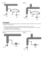
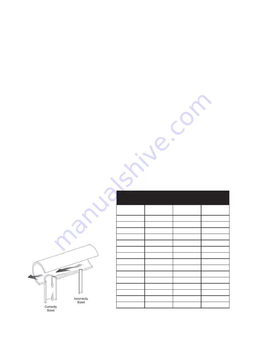
4. Proper piping and drip legs of adequate size and diameter are essential for the successful operation of the Armstrong
bimetallic traps, see
Chart 3-1 and Figure 3-1
.
5. Isolation valves are needed before and after traps. When starting a new trap, be sure to open the valve slowly.
6. Due to the high temperatures of steam, it might be necessary to guard the traps for personnel safety.
Figure 3-1
M
D
H
Drip Leg Length
Minimum (in)
Steam Main
Size (in)
Drip Leg
Diameter (in)
Supervised
Warm-Up
Automatic
Warm-Up
1/2
1/2
10
28
3/4
3/4
10
28
1
1
10
28
2
2
10
28
3
3
10
28
4
4
10
28
6
4
10
28
8
4
12
28
10
6
15
28
12
6
18
28
14
8
21
28
16
8
24
28
18
10
27
28
20
10
30
30
24
12
36
36
Chart 3-1


